


5–4 Upgrading the AlphaPC 164SX
Increasing Microprocessor Speed
5.3.3 Removing the 21164PC Microprocessor
Remove the microprocessor currently in place at location U31 by performing the
following steps:
1. Unplug the fan power/sensor cable from connector J14 (see Figure 2–1).
2. Remove the four 6–32 × 0.625-inch screws that secure the fan to the heat sink.
3. Remove the fan.
4. If the sink/chip/fan clip is used, remove it by unhooking its ends from around the
ZIF socket retainers.
5. Using a 3/8-inch socket, remove the two nuts securing the heat sink to the micro-
processor studs.
6. Remove the heat sink by gently lifting it off the microprocessor.
7. Remove and discard the GRAFOIL heat conduction pad.
8. Thoroughly clean the bottom surface of the heat sink before affixing it to the
new microprocessor.
9. Lift the ZIF socket actuator handle to a full 90° angle.
10. Remove the microprocessor chip by lifting it straight out of the socket.
5.3.4 Installing the 21164PC Microprocessor
Install the new microprocessor in location U31 by performing the following steps:
Note: Install the heat sink only after the microprocessor has been assembled to
the ZIF socket.
1. Observe antistatic precautions.
2. Lift the ZIF socket actuator handle to a full 90° angle.
3. Ensure that all the pins on the microprocessor package are straight.
4. The ZIF socket and microprocessor are keyed to allow for proper installation.
Align the microprocessor, with its missing AD01 pin, with the corresponding
plugged AD01 position on the ZIF socket. Gently lower into position.
5. Close the ZIF socket actuator handle to its locked position.
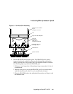
6. Install the heat sink and heat-sink fan as directed in the following steps. A heat-
sink/fan kit is available from the vendor listed in Appendix A. Refer to
Figure 5–1 for heat-sink and fan assembly details.