


Removal and Replacement Procedures
Maintenance and Service Guide 5–25
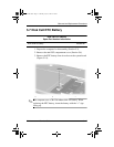
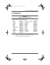
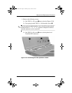
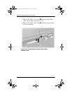
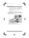
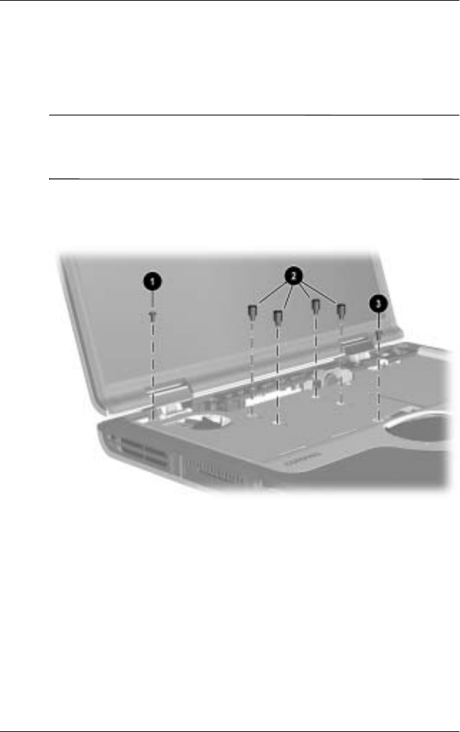
4. Remove the following screws:
❏
One TM2.5 × 5.0 screw
1
next to the fan (Figure 5-20)
❏
Four spring-loaded TM2.5 × 14.0 shoulder screws
2
✎
The four spring-loaded shoulder screws should be removed and
installed in the “1,” “2,” “3,” “4” sequence stamped on the heat
spreader adjacent to each screwhole.
❏
One TM2.5 × 8.0 screw
3
next to the keyboard and
TouchPad ZIF connectors
Figure 5-20. Removing the Heat Spreader Screws
272638-001.book Page 25 Thursday, July 25, 2002 4:21 PM