


5–32 Maintenance and Service Guide
Removal and Replacement Procedures
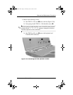
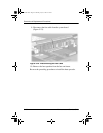
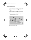
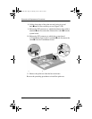
4. Remove the TM2.5 × 5.0 screw
1
that secures the display
inverter cable ground loop to the heat spreader (Figure 5-25).
5. Disconnect the display inverter cable
2
from the system
board.
6. Remove the TM2.5 × 5.0 screw
3
that secures the display
video cable ground loop to the heat spreader.
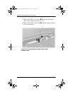
7. Disconnect the display video cable
4
from the system board.
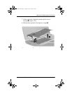
8. Remove the display video cable from the routing channels in
the heat spreader and the top cover
5
.
Figure 5-25. Removing the Display Screws and
Disconnecting the Display Cables
272638-001.book Page 32 Thursday, July 25, 2002 4:21 PM