


Removal and Replacement Procedures
Maintenance and Service Guide 5–55
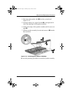
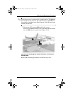
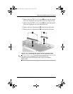
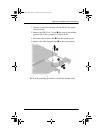
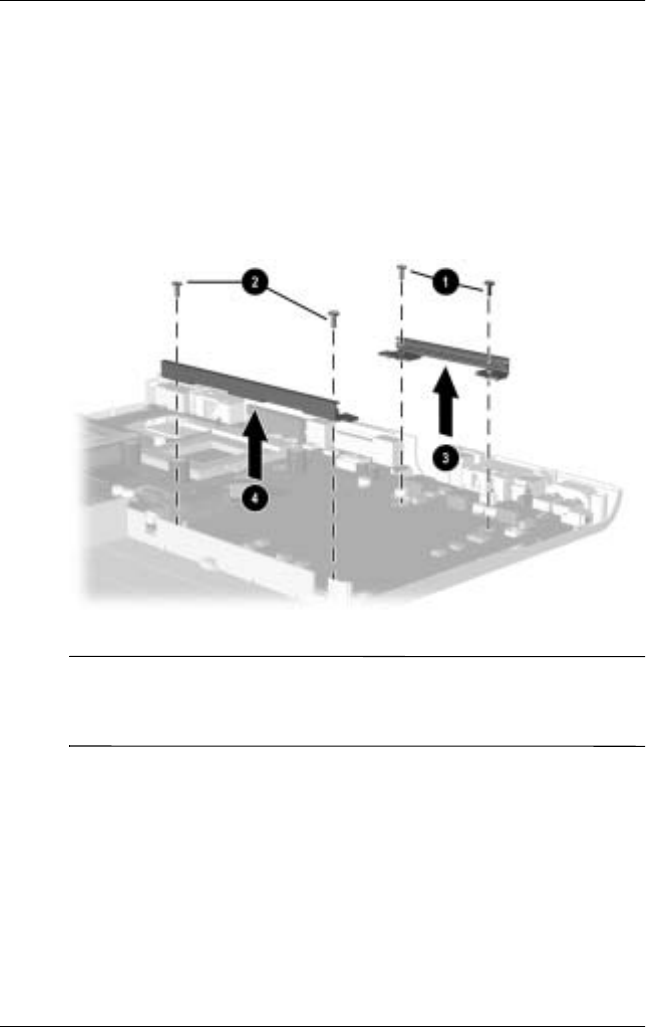
2. Remove the two TM2.5 × 5.0 screws
1
that secure the optical
drive rear alignment rail to the base enclosure (Figure 5-42).
3. Remove the two TM2.5 × 5.0 screws
2
that secure the optical
drive rear alignment rail to the base enclosure.
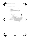
4. Remove the rear alignment rail
3
from the base enclosure.
5. Remove the rear alignment rail
4
from the base enclosure.
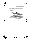
Figure 5-42. Removing the Optical Drive Alignment Rails
✎
The optical drive alignment rails are included in the
Miscellaneous Plastics/Hardware Kit, spare part number
285541-001.
272638-001.book Page 55 Thursday, July 25, 2002 4:21 PM