


5–56 Maintenance and Service Guide
Removal and Replacement Procedures
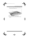
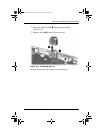
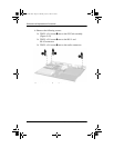
6. Remove the following screws:
❏
TM2.5 × 5.0 screw
1
next to the PC Card assembly
(Figure 5-43)
❏
TM2.5 × 5.0 screw
2
next to the RJ-11 and
RJ-45 connectors
❏
TM2.5 × 5.0 screw
3
next to the audio connectors
Figure 5-43. Removing the System Board Screws
272638-001.book Page 56 Thursday, July 25, 2002 4:21 PM