


Removal and replacement procedures
Maintenance and Service Guide 4–51
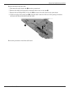
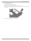
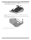
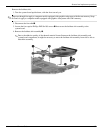
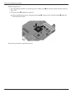
6. Lift the right side 1 of the system board until it rests at an angle 2.
7. Remove the system board by sliding it to the right at an angle 3 until the connectors on the left side of the
system board disengage from the base enclosure.
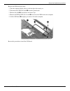
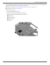
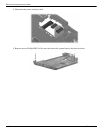
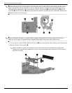
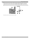
8. To replace the RJ-11 connector and cable, remove the RJ-11 connector 1 from the clip built into the base
enclosure.
9. Remove the cable 2 from the routing channel built into the base enclosure. The RJ-II connector and cable are
available using spare part number 494981-001.
Reverse this procedure to install the system board.