


4–54 Maintenance and Service Guide
Removal and replacement procedures
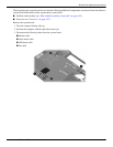
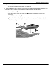
✎
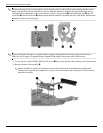
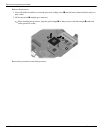
The thermal material must be thoroughly cleaned from the surface of the fan/heat sink assembly and the system
board each time the heat sink assembly is removed. Thermal material is applied to the discrete fan/heat sink to
correspond with components on the system board as follows: the processor
1
, the Northbridge chip
2
, the ATI
video chip
3
, and the capacitors
4
. Replacement thermal material is included with all system board, fan/heat sink
assembly, and processor spare parts.
✎
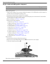
Steps two through four apply to computer models equipped with graphics subsystems with discrete memory.
Steps five and six apply to computer models equipped with graphics subsystems with UMA memory.
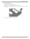
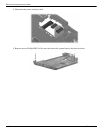
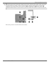
5. Loosen the four captive Phillips PM2.0×10.0 screws 1 that secure the heat sink assembly to the system board.
6. Remove the heat sink assembly 2.
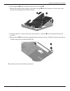
✎
Due to the adhesive quality of the thermal material located between the fan/heat sink assembly and
system board components, it might be necessary to move the fan/heat sink assembly from side to side to
detach the assembly.