iv
3 Removal and Replacement
3.1 Introduction ...................................................................................................... 3–1
3.2 Top Cover......................................................................................................... 3–3
3.3 Power Supply.................................................................................................... 3–4
Figures
Figure 1-1 Front Components ................................................................................. 1–2
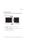
Figure 1-2 Operator Control Panel.......................................................................... 1–3
Figure 1-3 Rear Components .................................................................................. 1–4
Figure 2-1 Installation Area and Rail-Hole Pattern (EIA Rail-Hole Pattern) ........... 2–5
Figure 2-2 Attaching the Slide Assemblies to the Cabinet Rails.............................. 2–7
Figure 2-3 Attaching the Inner Slide Races............................................................. 2–9
Figure 2-4 Mounting the Memory Channel Hub, Front Bezel, and Interlock Actuator
Bracket on the Tray.............................................................................................2–11
Figure 2-5 Mounting the Chassis and Tray Assembly on the Slides .......................2–13
Figure 2-6 The Interlock System............................................................................2–16
Figure 3-1 Removing and Replacing the Top Cover ............................................... 3–3
Figure 3-2 Removing the Power Supply.................................................................. 3–4
Figure 3-3 Disconnecting the Power Cable Connector and Removing the Power
Supply.................................................................................................................. 3–5
Tables
Table 1-1 2T-CCMHA-CB Central Office Memory Channel Hub Specifications... 1–5
Table 2-1 Mounting Hardware and Component List ............................................... 2–3


