


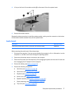
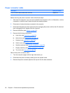
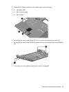
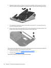
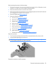
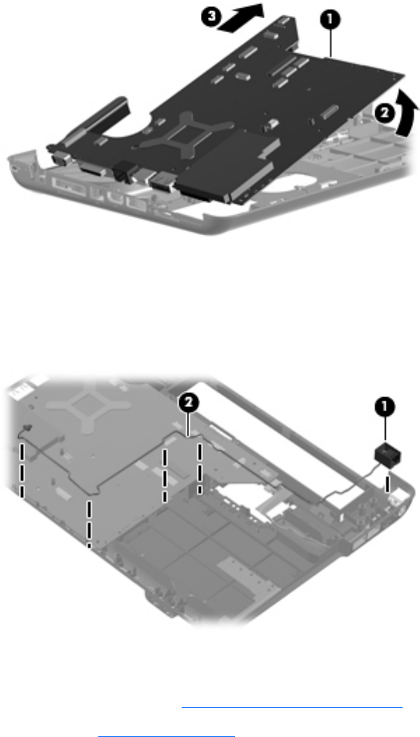
6. Release the system board by sliding it to the right at an angle (3) until the connectors on the left
side of the system board disengage from the base enclosure, and then remove the system board.
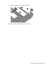
7. If it is necessary to replace the modem module cable, remove the RJ-11 connector (1) from the
clip built into the base enclosure.
8. Remove the modem module cable (2) from the routing channel built into the base enclosure. The
modem module cable is available using spare part number 494981-001.
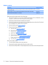
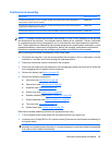
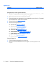
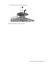
When replacing the system board, be sure that the following components are removed from the defective
system board and installed on the replacement system board:
●
Fan/heat sink assembly (see
Fan/heat sink assembly on page 85)
●
Processor (see
Processor on page 88)
Reverse the preceding procedure to install the system board.
84 Chapter 4 Removal and replacement procedures