


Fan/heat sink assembly
Description Spare part number
Fan/heat sink assembly for use in computer models with Intel processors with UMA graphics
subsystems (includes thermal material)
486838-001
Fan/heat sink assembly for use in computer models with Intel processors with discrete graphics
subsystems (includes thermal material)
486839-001
Fan/heat sink assembly for use in computer models with AMD processors (includes thermal material) 492260-001
NOTE: To properly ventilate the computer, allow at least a 7.6-cm (3-inch) clearance on the right side
and rear panel of the computer. The computer uses an electric fan for ventilation. The fan is controlled
by a temperature sensor and is designed to turn on automatically when high temperature conditions
exist. These conditions are affected by high external temperatures, system power consumption, power
management/battery conservation configurations, battery fast charging, and software requirements.
Exhaust air is displaced through the ventilation grill located on the left side of the computer.
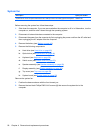
Before removing the fan/heat sink assembly, follow these steps:
1. Shut down the computer. If you are unsure whether the computer is off or in Hibernation, turn the
computer on, and then shut it down through the operating system.
2. Disconnect all external devices connected to the computer.
3. Disconnect the power from the computer by first unplugging the power cord from the AC outlet and
then unplugging the AC adapter from the computer.
4. Remove the battery (see
Battery on page 43).
5. Remove the following components:
a. Hard drive (see
Hard drive on page 46)
b. Optical drive (see
Optical drive on page 44)
c. Keyboard (see
Keyboard on page 56)
d. Switch cover (see
Switch cover on page 58)
e. Speaker assembly (see
Speaker assembly on page 60)
f. Display assembly (see
Display assembly on page 62)
g. Top cover (see
Top cover on page 69)
h. System board (see
System board on page 82)
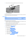
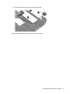
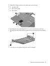
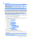
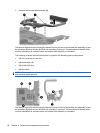
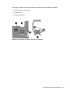
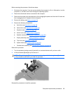
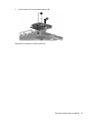
Remove the fan/heat assembly (fan/heat sink appearance may vary):
1. Turn the system board upside down with the external monitor port toward you.
2. Loosen the four Phillips PM2.0×10.0 captive screws (1) that secure the fan/heat sink assembly to
the system board.
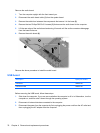
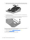
NOTE: Due to the adhesive quality of the thermal material located between the fan/heat sink
assembly and system board components, it may be necessary to move the fan/heat sink assembly
from side to side to detach the assembly.
Component replacement procedures 85