


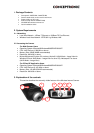

1. Screw Hole
Located on the top/bottom panel of the camera, the screw hole is used to
connect the camera stand onto the camera by attaching the screw head on
the camera stand into the screw hole of the camera.
2. Power and Link LED
The Power LED
is positioned on the right side of the Wireless Internet
Camera’s lens while facing the Wireless Internet Camera. A steady BLUE
light confirms that the Wireless Internet Camera is powered on.
The Link LED
is positioned on the right side of the Wireless Internet
Camera’s lens while facing the Wireless Internet Camera. It is located right of
the Power LED. A steady ORANGE light confirms that the camera has good
connection to LAN connectivity. Dependent on the data traffic the LED will
begin to flash to indicate that the Wireless Internet Camera is
receiving/sending data from/to the network.
3. Lens Cap
By turning the Lens Cap to the right or the left, you can adjust the sharpness
of the recording image.
4. Network Cable Connector
The Wireless Internet Camera’s rear panel features an RJ-45 connector for
connections to 10Base-T Ethernet cabling or 100Base-TX Fast Ethernet
cabling (which should be Category 5 twisted-pair cable). The port supports
the N-Way protocol and “Auto-MDIX” function, allowing the Wireless Internet
Camera to automatically detect or negotiate the transmission speed of the
network.
5. External Antenna (Only on C54NETCAM)
The rotatable external antenna allows you to adjust its position to obtain the
maximum signal.
6. Reset Button
Reset will be initiated when the reset button is pressed once, and Power
LED begins to flash.
Factory Reset will be initiated when the reset button is pressed continuously
for three seconds or when Power LED begins to light up. Release the reset
button and the Power LED will begin to flash, indicating the Wireless Internet
Camera is changing to factory reset. When factory reset is completed, the
Wireless Internet Camera will be set to de fault on channel 11 and SSID is
set as “NULL String” (This default setting will let the Wireless Internet Camera
connect to ANY access point on the infrastructure network). The IP address
will also return to the default setting as 192.168.0.20.
7. DC Power Connector
The DC power input connector is located on the Wireless Internet Camera’s
rear panel, and is la beled DC5V with a single jack socket to supply power to
the Wireless Internet Camera. Power will be generated when the power
supply is connected to a wall outlet.