


Chapter 4: Appendix D - RS-485/422 Option 4-19
Intellicon-NT960/PCI User's Manual, ver. 0.02
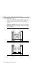
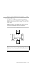
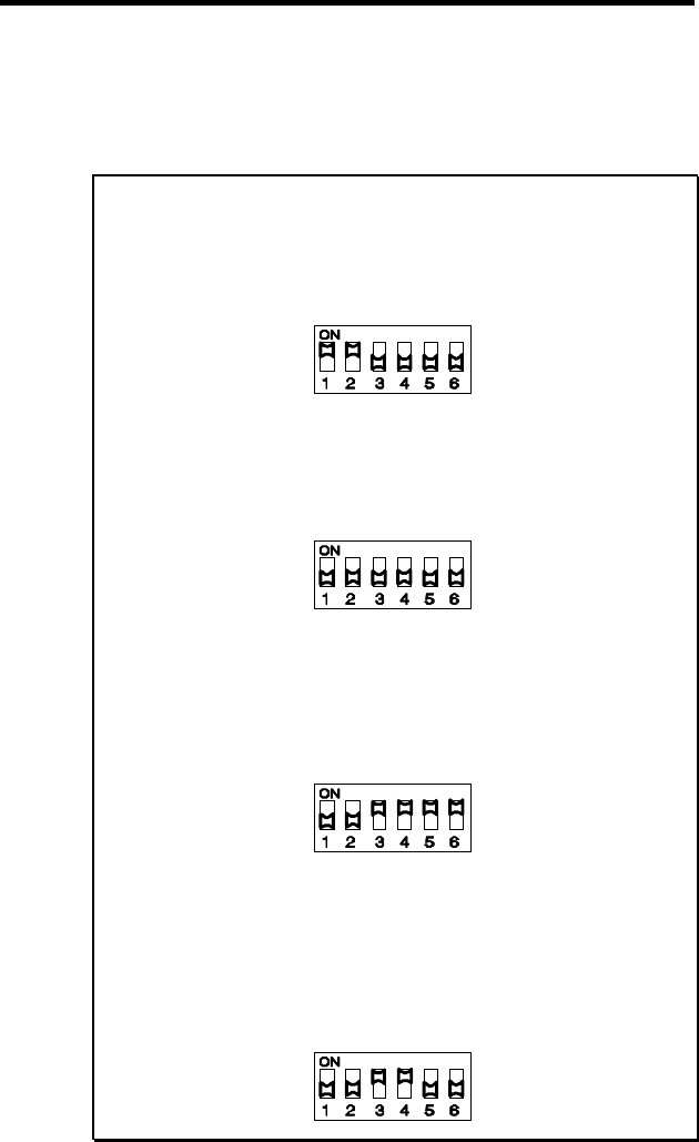
Switch positions 5 and 6 on switch blocks S1, S2, S3, and S4
allow the "receiver stations" (RxD and CTS) to have either a DC
load of 150 ohms or an AC load of 150 ohms in series with a 50
nF capacitor. Please refer to the examples following for these
configuration options and their switch settings.
Examples:
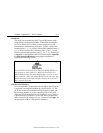
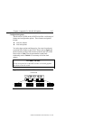
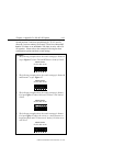
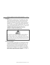
1. The following example shows the switch settings for Station A
as per Figure 17 where TxD and RTS have a load of 150
Ω
.
switch blocks
S1, S2, S3, or S4
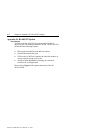
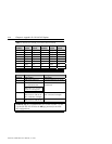
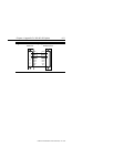
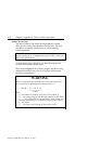
2. The following example shows the switch settings for Station B
and Station C as per Figure 17.
switch blocks
S1, S2, S3, or S4
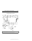
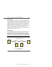
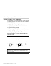
3. The following example shows the switch settings for Station
D as per Figure 17 where RxD and CTS have a DC load of
150
Ω
..
switch blocks
S1, S2, S3, or S4
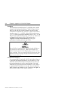
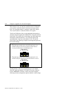
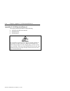
4. The following example shows the switch settings for Station
D as per Figure 17 where the circuit is > than 50 metres in
length and RxD and CTS have an AC load of 150
Ω
in series
with 50 nF.
switch blocks
S1, S2, S3, or S4