


Crestron CNX-PVID8x4 Professional Video Distribution Switch
Operations Guide - DOC. 8166A Professional Video Distribution Switch: CNX-PVID8x4 • 7
NET
This 4-pin terminal block connector is used to connect the CNX-PVID8x4 to the
Cresnet
®
system. Refer to "Network Wiring" on page 8 for details.
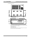
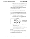
CNX-PVID8x4 Indicators
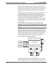
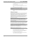
There are 30 LED indicators located on the front panel of the CNX-PVID8x4, and
one on the back panel. Refer to the following illustration and descriptions.
CNX-PVID8x4 Indicators
I
PWR
NET
CRESTRON
RTSIDOEDIVLANOISSEFORP
TIAV UEVPIECNOTDI
13452678
10987654321 1614131211 15
3
LESCTE
2
1
4
B HCTIWSNOITU
UTPUOT
CNX-PVID8X4
PWR (Power)
This LED illuminates when 24 volts DC from the network is supplied to the
CNX-PVID8x4.
NET
This LED illuminates when communication between the Cresnet system and the
CNX-PVID8x4 is established (unit is polled on the network). Illumination indicates
that the SIMPL Windows program currently loaded has a network device defined at
the same Net ID as the CNX-PVID8x4.
SELECT 1 - 4
These LEDs illuminate when a switcher board (levels 1 through 4) is selected.
Boards can be locally selected with a pushbutton. Refer to "CNX-PVID8x4
Pushbuttons" on this page for details.
OUTPUT 1 - 8
These eight LEDs illuminate to indicate that a source is routed via the respective port
to the corresponding room.
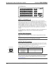
ACTIVE VIDEO INPUT
These 16 video sync indicators illuminate to signify active inputs on the selected
board (level).
NOTE: Only composite video and the "Y" S-video/component signal are reliably
detected. If connections to the INPUT connectors are made as recommended by
Crestron in "Hardware Configurations" on page 14, simply use level 1 for detection
of the sync signals.