Professional Video Distribution Switch Crestron CNX-PVID8x4
8 • Professional Video Distribution Switch: CNX-PVID8x4 Operations Guide - DOC. 8166A
SETUP
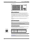
This LED is the lone indicator on the back panel. The LED is intended for future use
and is not defined at the time of printing.
CNX-PVID8x4 Pushbuttons
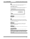
There are two pushbuttons on the CNX-PVID8x4 (one on the front panel and one on
the back panel). The front panel SELECT pushbutton allows for local selection of
the boards (levels 1 through 4). Four indicators are used as feedback. The rear panel
SETUP pushbutton is for future use and is not defined at the time of printing.
Industry Compliance
As of the date of manufacture, the CNX-PVID8x4 has been tested and found to
comply with specifications for CE marking and standards per EMC and
Radiocommunications Compliance Labelling.
NOTE: This device complies with part 15 of the FCC rules. Operation is subject to
the following two conditions: (1) these devices may not cause harmful interference,
and (2) these devices must accept any interference received, including interference
that may cause undesired operation.
Setup
Network Wiring
CAUTION: Use only Crestron power supplies for Crestron equipment. Failure to
do so could cause equipment damage or void the Crestron warranty.
NOTE: When installing network wiring, refer to the latest revision of the wiring
diagram(s) appropriate for your specific system configuration, available from the
Downloads | Product Manuals | Wiring Diagrams section of the Crestron website
(www.crestron.com).
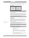
When calculating the wire gauge for a particular Cresnet run, the length of the run
and the power factor of each network unit to be connected must be taken into
consideration. If Cresnet units are to be daisy-chained on the run, the power factor of
each unit to be daisy-chained must be added together to determine the power factor
of the entire chain. If the unit is a home-run from a Crestron system power supply
network port, the power factor of that unit is the power factor of the entire run. The
length of the run in feet and the power factor of the run should be used in the
following resistance equation to calculate the value on the right side of the equation.
Resistance Equation
R = Resistance (refer to table below).
L = Length of run (or chain) in feet.
PF = Power factor of entire run (or chain).
R <
L x PF
40,000
Where:


