


Professional Video Distribution Switch Crestron CNX-PVID8x4
12 • Professional Video Distribution Switch: CNX-PVID8x4 Operations Guide - DOC. 8166A
• When mounting this unit in a partially filled rack, load the rack from
the bottom to the top with the heaviest component at the bottom of the
rack.
• If the rack is provided with stabilizing devices, install the stabilizers
before mounting or servicing the units in the rack.
NOTE: If rack mounting is not required, rubber feet are provided for tabletop
mounting or stacking. Apply the feet near the corner edges on the underside of the
unit. Refer to "Stacking" on page 12 for details.
NOTE: Reliable grounding of rack-mounted equipment should be maintained.
Particular attention should be given to supply connections other than direct
connections to the branch circuit (e.g., use of power strips).
Two "ears" are provided with the CNX-PVID8x4 so that the unit can be rack
mounted. These ears must be installed prior to mounting. Complete the following
procedure to attach ears to the CNX-PVID8x4. The only tool required for this
procedure is a #2 Phillips screwdriver.
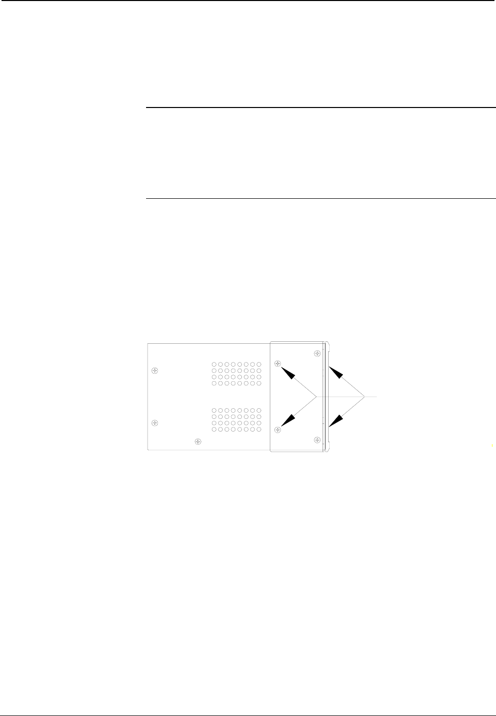
1. Position a rack ear so that its drilled holes align with the four vacated
holes located on one side of the CNX-PVID8x4.
2. Use four screws (supplied, #6-32, 3/8"L) to secure the ear to the
CNX-PVID8x4, as shown in the following diagram.
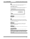
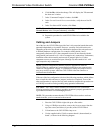
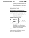
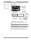
Ear Attachment for Rack Mounting (Side View of Unit)
FASTEN EACH EAR
WITH FOUR
SCREWS (SUPPLIED)
3. Tighten screws to finger-tight then, using a #2 Phillips screwdriver,
tighten an additional 1/8-turn.
4. Repeat procedure (steps 1 and 2) to attach ear to the other side.
5. If the rear panel of the CNX-PVID8x4 is accessible when mounted in
the rack, install the CNX-PVID8x4. If the rear panel is NOT accessible,
perform the hookup procedure before rack installation.
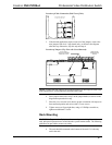
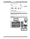
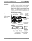
Stacking
Four "feet" are provided with the CNX-PVID8x4 so that if the unit is not rack
mounted, the rubber feet can provide stability when the unit is placed on a flat
surface or stacked. These feet should be attached prior to the hookup procedure.
Refer to the following illustration for placement of the feet.