


Power Switching CRESTRON GREEN LIGHT™
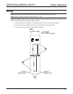
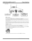
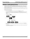
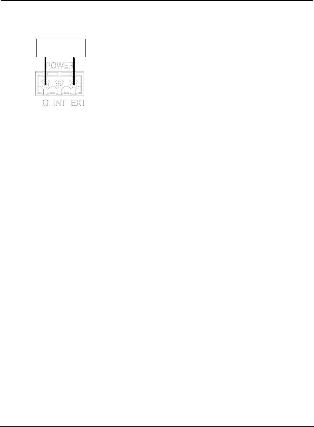
To power the modules externally from a Cresnet 24 VDC power supply, connect the external power supply to
the EXT and G pins on the POWER supplied connector as shown in the following diagram.
Providing Cresnet Power Externally
CRESTRON 24 VDC
POWER SUPPLY
G 24
When properly connected and receiving 24 VDC power externally, the green LED next to the MODULES port
will light.
When a lighting module is powered from a Cresnet power supply in the absence of line power, the module’s
PWR LED will flash.
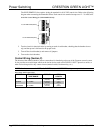
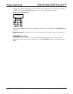
OVERRIDE Port Wiring
Low-voltage input devices such as the Crestron GLS-PLS-120/277 phase-loss sensor or any device that
provides a dry contact closure can be connected to the supplied OVERRIDE connector on the bottom of the
cabinet.
10 • CRESTRON GREEN LIGHT Power Switching Installation Guide – DOC. 6672B