


CRESTRON GREEN LIGHT™ Power Switching
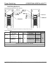
Load Wiring (Section B)
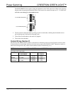
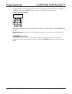
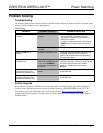
CAUTION: Bypass jumpers are provided on each output to allow testing and to protect the module during
installation. The jumper shorts the L and SW terminals so that the load circuit is energized when the branch breaker
is on. Do not remove the bypass jumper until all feed and load wiring has been completed, and the circuits have been
tested for electrical faults.
NOTE: Use copper conductors only – rated 75°C.
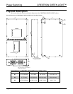
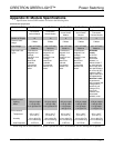
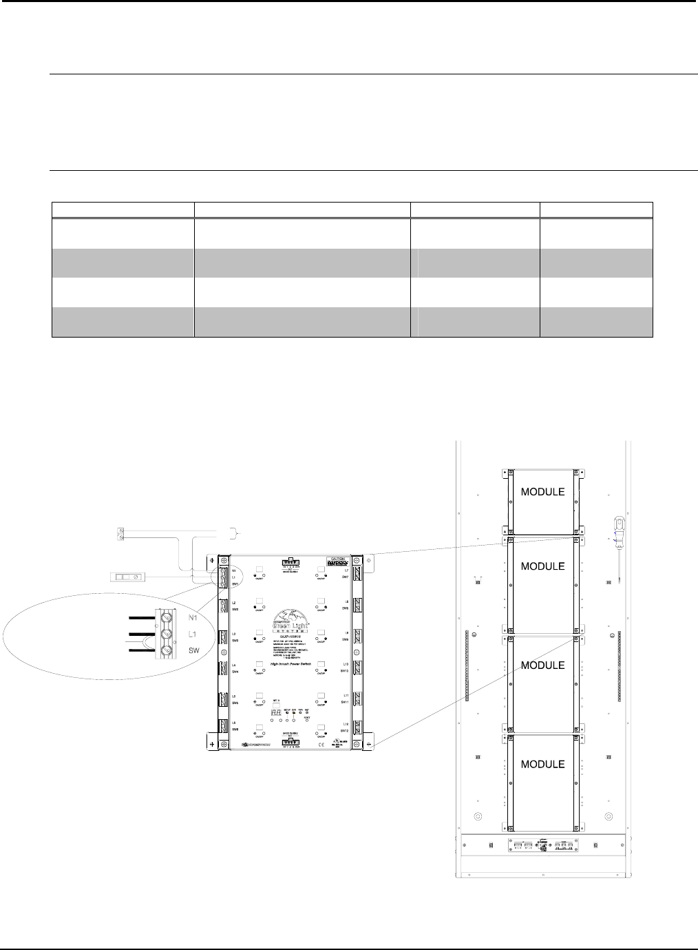
Wire Gauge and Torque Values
TERMINAL CONNECTOR MAX WIRE RANGE TORQUE STRIP LENGTH
LOAD OUTPUTS 14-10 AWG 4.43 lb-in
(0.5 Nm)
5/16”
(8 mm)
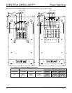
DIM CONTROL
(GLXP-DIMFLV8 only)
28-12 AWG 4.43 lb-in
(0.5 Nm)
5/16”
(8 mm)
GROUND BAR 14-10 AWG 35 lb-in
(4.0 Nm)
5/16”
(8 mm)
GROUND LUG 14-4 AWG 45-25 lb-in
(5.1-2.8 Nm)
3/4"
(19 mm)
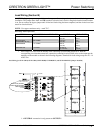
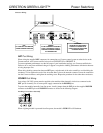
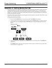
1. Each output has a label with the number of the controlling circuit breaker printed on it. With the
corresponding circuit breaker turned off, connect the controlled circuit (LOAD) wires to the output per the
markings on the module as shown in the following diagrams. Terminals for load wiring accept one 10 – 14
AWG wire.
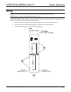
Load Wiring for GLXP-SW10, GLXP-SW16, GLXP-HSW8, GLXP-HSW12, and GLXP-DIMFLV8 (Jumper Installed)
1.2000
L
CIRCUIT BREAKER (20A MAX)
NEUTRAL
BUS
TO LOADS
1
2
N
L
TO NEUTRAL BUS (PREWIRED)*
TO BRANCH BREAKER (PREWIRED)
TO LOAD
JUMPER (PREWIRED)
3
4
* A NEUTRAL connection is only present on OUTPUT 1.
Installation Guide – DOC. 6672B CRESTRON GREEN LIGHT Power Switching • 7