


CRESTRON GREEN LIGHT™ Power Switching
Wiring
NOTE: All wiring must be installed in accordance with all local and national electrical codes.
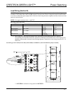
NOTE: Refer to the torque settings specified on pages 6, 7 and 8.
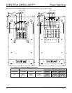
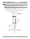
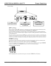
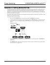
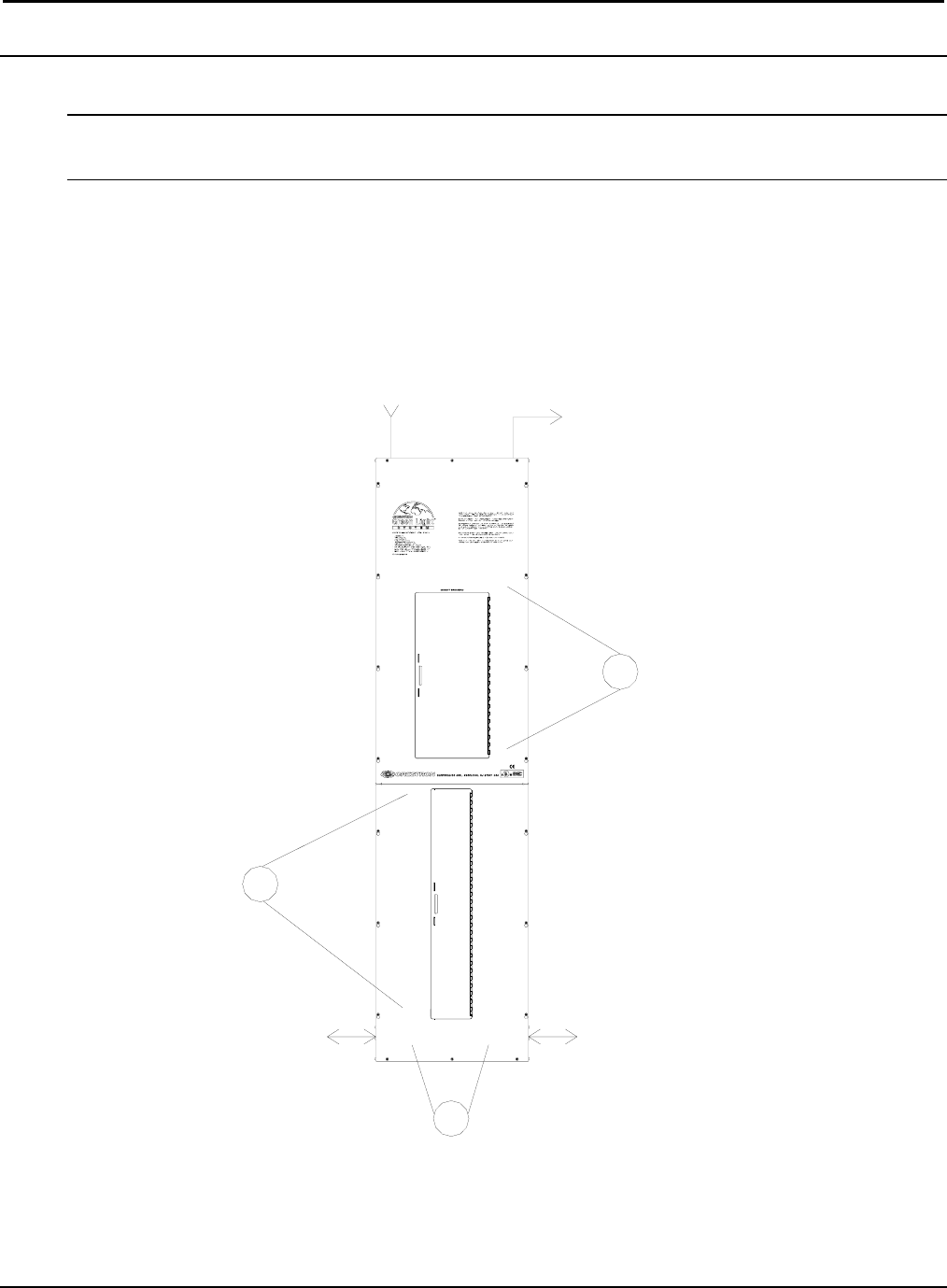
CRESTRON GREEN LIGHT cabinets are shipped with GLXP modules installed and prewired to the branch circuit
breakers. The following must be performed after installation:
• Connect incoming feed conductors to the breaker panel (section A of the following diagram)
• Connect load wiring to GLXP module outputs (section B of the following diagram)
• Connect control wiring (section C of the following diagram)
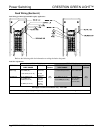
CLASS 2
WIRING ONLY
CLASS 2
WIRING ONLY
A
B
C
FEED:
3-PHASE 4-WIRE
TO LOADS:
2W + GND 16A (MAX)
Installation Guide – DOC. 6672B CRESTRON GREEN LIGHT Power Switching • 5