


Isys
®
G-Series Touchpanels Crestron TPS-12G/15G/17G-QM
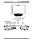
4. The TPS-12G-QM can be powered via the 24 VDC jack or the NET port. Be sure to use a Crestron
approved power supply as another may cause damage. The TPS-17G-QM connects to the Cresnet
control network and remote power supply via the TPS-17G-QM/-L-IMC Power Interface Module
(included with the TPS-17G-QM).
CAUTION: Do not connect the TPS-17G-QM directly to the Cresnet network bus.
5. This port not used by the TPS-15G-QM, which instead, must be powered via Cresnet connector only,
using CNPWS-75 or C2N-SPWS300 power supply (sold separately). The TPS-17G-QM may be
powered via this port or via the TPS-17G-QM/-L-IMC Power Interface Module (included) using the
power supply provided.
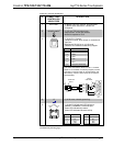
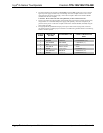
6. The eight-pin RJ-45 QuickMedia transport port accepts CAT5E/CAT6 carrying audio, video and
microphone signals. The QM input port conforms to the 568B wiring standard. Refer to the following
table for connector pinouts.
RJ-45 PIN
NUMBER
WIRE COLORS
(EIA 568B)
QM ASSIGNMENT: RGB
QM ASSIGNMENT: COMPOSITE,
S-VIDEO, COMPONENT AND
AUDIO
1 WHITE/ORANGE
- RGB RED
- CHROMINANCE (- P
r
)
2 ORANGE
+ RGB RED
+ CHROMINANCE (+ P
r
)
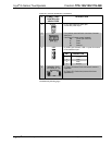
3 WHITE/GREEN
- RGB GREEN
- LUMINANCE (- Y)
4 BLUE
+ DIGITAL AUDIO
+ AUDIO
5 WHITE/BLUE
- DIGITAL AUDIO
- AUDIO
6 GREEN
+ RGB GREEN
+ LUMINANCE (+ Y)
7 WHITE/BROWN
- RGB BLUE
- COMPOSITE (- P
b
)
8 BROWN
+ RGB BLUE
+ COMPOSITE (+ P
b
)
18 • Isys
®
G-Series Touchpanels: TPS-12G/15G/17G-QM Operations Guide – DOC. 6415B