


CPBH Series CyberResearch
®
CPU Cards
20 ©Copyright 2005 CyberResearch, Inc
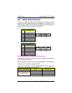
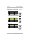
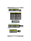
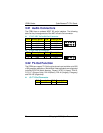
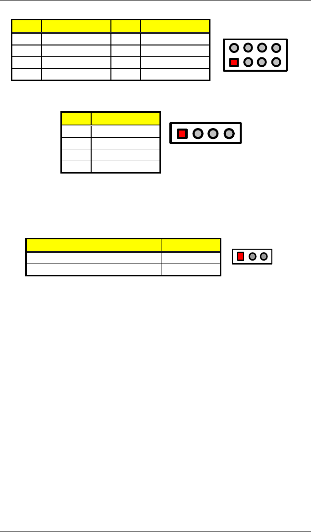
z CN13: USB4/USB5 Connector
PIN Description
PIN
Description
1 VCC 2 VCC
3 BD5- 4 BD4-
5 BD5+ 6 BD4+
7 GND 8 GND
VCC
1
2
7
8
VCC
BD4-
BD4+
GND
BD5-
BD5+
GND
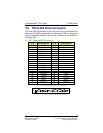
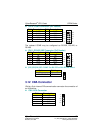
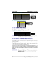
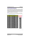
z CN19: External USB Connector
PIN Description
1 VCC
3 BD6-
5 BD6+
7 GND
14
VCC
BD6-
BD6+
GND
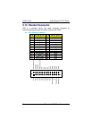
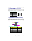
3.16 CMOS Data Clear
The CPBH has a Clear CMOS jumper on JP3.
z JP3: Clear CMOS
Optional Settings
Normal Operation (default) Short 1-2
Clear CMOS Short 2-3
13
IMPORTANT: Before you turn on the power of your system, please
set JP3 to short 1-2 for normal operation.
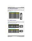
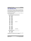
3.17 Power and Fan Connectors
The CPBH provides one 4-pin and one 20-pin ATX power connectors
at CN1 and CN5.
The CPBH must use P4 power supply. One of 4-pin connectors is for
+12V lead which should be connected to CN1.
A 20-pin ATX Power Connector can be connected to Backplane or to
CN5. If a 20-pin ATX Power Connector connects to Backplane, please
make sure CN23 and Backplane’s 5-pin ATX controller is connected
together!
IMPORTANT: Please plug CN1 (4-pin ATX power connector) before
CN5 (20-pin ATX power connector) for protecting
hardware circuit.