© 2007 Cypress Solutions
Installation and Operation Manual: CTM-130 / CTM-132 (Revision 1.2)
Page - 14 -
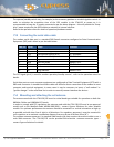
The operate/standby switch may, for example, be the accessory position on a vehicle ignition switch. In
order to minimize the acquisition time of the GPS module in the CTM-132 at power on it is
recommended to keep the +V supply connected as per the above diagram – this will provide the “keep-
alive” power required by the GPS module to maintain its internal almanac.
Refer to the operation notes for details of operation/shutdown modes.
7.3 Connecting the serial data cable
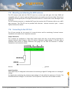
The modem serial data port is a standard DB9 female connector configured as Data Communication
Equipment (DCE) and is wired as per the table below.
DB9 Pin
Signal
Name
Direction
1
DCD
Data Carrier Detect
Modem PC
2
RxD
Received Data (by DTE)
Modem PC
3
TxD
Transmitted Data (by DTE)
PC Modem
4
DTR
Data Terminal Ready
PC Modem
5
GND
Signal Ground
6
DSR
Data Set Ready
Modem PC
7
RTS
Request To Send
PC Modem
8
CTS
Clear To Send
Modem PC
9
RI
Ring Indicator
Modem PC
The DTR signal (pin 4) is used for modem operation/standby control - refer to the operation notes for
details.
Serial data ports on most computer equipment are configured as Data Terminal Equipment (DTE) with a
DB9 male connector. A standard serial data cable will allow for direct connection of the modem to most
computer and terminal equipment. In some cases it may be necessary to insert a “null modem” or
“gender changer” in the serial data line in order to correctly connect between the devices.
7.4 Mounting and attaching the cell antenna
The antenna used with the CTM-130/132 must be a dual band type suitable for operation on both the
800MHz Cellular and 1900MHz PCS bands.
In order to comply with FCC regulations the antenna used with the CTM-130/132 must be an approved
model such as the MaxRad model MDBM 800/1900 – contact Cypress Solutions for other suitable
models. For optimum performance the antenna should be mounted in a vertical orientation as high up
as possible and with clear line of sight in all directions. For regulatory purposes it must be mounted in
such a position as to maintain a separation distance from any person of at least 20cm (8”).
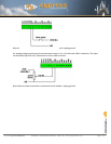
The modem antenna connector is a standard SMA female type that requires the antenna cable to use a
male SMA connector. The CTM-130/132 can be provided with alternate antenna connector types –
contact Cypress Solutions for details.


