CY7C68300C/CY7C68301C
CY7C68320C/CY7C68321C
Document 001-05809 Rev. *A Page 39 of 42
General PCB Layout Recommendations For USB Mass Storage Designs
The following recommendations must be followed to ensure
reliable high-performance operation:
• Use at least a four-layer, impedance controlled board to
maintain signal quality.
• Specify specific impedance targets (ask your board vendor
what they can achieve).
• Maintain uniform trace widths and trace spacing to control
impedance.
• Minimize reflected signals by avoiding using stubs and vias.
• Connect the USB connector shell and signal ground as near
to the USB connector as possible.
• Use bypass/flyback capacitors on VBUS near the
connector.
• Keep DPLUS and DMINUS trace lengths to within 2 mm of
each other in length, with a preferred length of 20–30 mm.
• Maintain a solid ground plane under the DPLUS and
DMINUS traces. Do not allow the plane to be split under
these traces.
• Do not place vias on the DPLUS or DMINUS trace routing
for a more stable design.
• Isolate the DPLUS and DMINUS traces from all other signal
traces by no less than 10 mm.
• Source for recommendations:
• EZ-USB FX2LP PCB Design Recommendations
http://www.cypress.com
• High-speed USB Platform Design Guidelines
http://www.usb.org
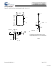
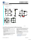
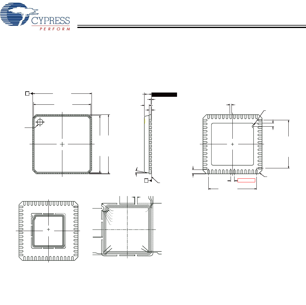
Figure 14. 56-Lead QFN 8 x 8 mm LF56A
Package Diagrams (continued)
0.80[0.031]
7.70[0.303]
7.90[0.311]
A
C
1.00[0.039] MAX.
N
SEATING PLANE
N
2
0.18[0.007]
0.50[0.020]
1
1
0.08[0.003]
0.50[0.020]
0.05[0.002] MAX.
2
(4X)
C
0.24[0.009]
0.20[0.008] REF.
0.80[0.031] MAX.
PIN1 ID
0°-12°
6.45[0.254]
8.10[0.319]
7.80[0.307]
6.55[0.258]
0.45[0.018]
0.20[0.008] R.
8.10[0.319]
7.90[0.311]
7.80[0.307]
7.70[0.303]
DIA.
0.28[0.011]
0.30[0.012]
6.55[0.258]
6.45[0.254]
0.60[0.024]
N
1
2
TOP VIEW
BOTTOM VIEW
SIDE VIEW
E-PAD
(PAD SIZE VARY
BY DEVICE TYPE)
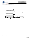
OPTION FOR CML - BOTTOM VIEW
NOTE:
DIMENSIONS ARE SAME WITH STD DWG ON UPPER RIGHT EXCEPT
FOR THE U-GROOVE ON THE PADDLE
.000
1.925
.000
2.375
2.325
R.250
(3X)
2.275
2.175
2.075
1.975
2.225
2.125
R.400
R.300
R.200
R.100
R.600
R.500
R.400
R.300
R.100
R.200
PIN #1 ID
.680
.240TYP
.680
U-GROOVE DIMENSION
E-PAD
(PAD SIZE VARY
BY DEVICE TYPE)
DIMENSIONS IN MM[INCHES] MIN.
MAX.
REFERENCE JEDEC MO-220
51-85144 *F
[+] Feedback


