


CYV15G0404DXB
Document #: 38-02097 Rev. *B Page 17 of 44
through the FRAMCHARx latches through the configuration
interface.
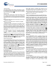
The specific bit combinations of these framing characters are
listed in Table 6. When the specific bit combination of the
selected framing character is detected by the framer, the bound-
aries of the characters present in the received data stream are
known.
Framer
The framer on each channel operates in one of three different
modes. Each framer is enabled or disabled using the RFENx
latches using the configuration interface. When the framer is
disabled (RFENx = 0), no combination of received bits alters the
frame information.
When the low latency framer is selected (RFMODEx[1:0] = 00),
the framer operates by stretching the recovered character clock
until it aligns with the received character boundaries. In this
mode the framer starts its alignment process on the first
detection of the selected framing character. To reduce the impact
on external circuits that use the recovered clock, the clock period
is not stretched by more than two bit periods in any one clock
cycle. When operated with a character rate output clock, the
output of properly framed characters may be delayed by up to
nine character clock cycles from the detection of the selected
framing character. When operated with a half character rate
output clock, the output of properly framed characters may be
delayed by up to 14 character clock cycles from the detection of
the framing character.
When RFMODEx[1:0] = 10, the Cypress-Mode Multi-Byte framer
is selected. The required detection of multiple framing characters
makes the associated link much more robust to incorrect framing
due to aliased SYNC characters in the data stream. In this mode,
the framer does not adjust the character clock boundary, but
instead aligns the character to the already recovered character
clock. This ensures that the recovered clock does not contain
any significant phase changes or hops during normal operation
or framing, and allows the recovered clock to be replicated and
distributed to other external circuits or components using
PLL-based clock distribution elements. In this framing mode the
character boundaries are only adjusted if the selected framing
character is detected at least twice within a span of 50 bits, with
both instances on identical 10-bit character boundaries.
When RFMODEx[1:0] = 01, the Alternate-mode Multi-Byte
Framer is enabled. Like the Cypress-mode Multi-Byte Framer,
multiple framing characters must be detected before the
character boundary is adjusted. In this mode, the data stream
must contain a minimum of four of the selected framing
characters, received as consecutive characters, on identical
10-bit boundaries, before character framing is adjusted.
10B/8B Decoder Block
The decoder logic block performs two primary functions:
■ Decoding the received transmission characters to data and
special character codes
■ Comparing generated BIST patterns with received characters
to permit at-speed link and device testing
The framed parallel output of each deserializer shifter is passed
to its associated 10B/8B Decoder where, if the decoder is
enabled, the input data is transformed from a 10-bit transmission
character back to the original data or special character code.
This block uses the 10B/8B decoder patterns in Table 14 and
Table 15. Received special code characters are decoded using
Table 15. Valid data characters are indicated by a 000b bit
combination on the associated RXSTx[2:0] status bits, and
special character codes are indicated by a 001b bit combination
of these status outputs. Framing characters, invalid patterns,
disparity errors, and synchronization status are presented as
alternate combinations of these status bits.
When DECBYPx = 0, the 10B/8B decoder is bypassed through
the configuration interface. When bypassed, raw 10-bit
characters are passed through the receiver and presented at the
RXDx[7:0] and the RXSTA[1:0] outputs as 10-bit wide
characters.
When the decoder is enabled by setting DECBYPx = 1 through
the configuration interface, the 10-bit transmission characters
are decoded using Table 14 and Table 15. Received Special
characters are decoded using Table 15. The columns used in
Table 15 are determined by the DECMODEx latch through the
device configuration interface. When DECMODEx = 0 the
ALTERNATE table is used and when DECMODEx = 1 the
CYPRESS table is used.
Receive BIST Operation
The receiver channel contains an internal pattern checker that
can be used to validate both device and link operation. These
pattern checkers are enabled by the associated RXBISTx latch
using the device configuration interface. When enabled, a
register in the associated receive channel becomes a signature
pattern generator and checker by logically converting to a Linear
Feedback Shift Register (LFSR). This LFSR generates a
511-character or 526-character sequence that includes all data
and special character codes, including the explicit violation
symbols. This provides a predictable yet pseudo random
sequence that can be matched to an identical LFSR in the
attached transmitters. When synchronized with the received
data stream, the associated Receiver checks each character in
the Decoder with each character generated by the LFSR and
indicates compare errors and BIST status at the RXSTx[2:0] bits
of the Output Register.
When BIST is first recognized as being enabled in the Receiver,
the LFSR is preset to the BIST-loop start code of D0.0. This code
D0.0 is sent only once per BIST loop. The status of the BIST
progress and any character mismatches are presented on the
RXSTx[2:0] status outputs.
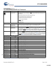
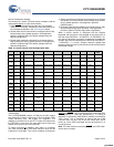
Table 6. Framing Character Selector
FRAMCHARx
Bits Detected in Framer
Character Name Bits Detected
0 COMMA+
COMMA–
00111110XX
[10]
or 11000001XX
1–K28.5
+K28.5
0011111010 or
1100000101
Note
10.The standard definition of a Comma contains only seven bits. However, since all valid Comma characters within the 8B/10B character set also have the eighth
bit as an inversion of the seventh bit, the compare pattern is extended to a full eight bits to reduce the possibility of a framing error.
[+] Feedback [+] Feedback