


CYV15G0404DXB
Document #: 38-02097 Rev. *B Page 37 of 44
mission of any transmission character, the transmitter selects the
proper version of the transmission character based on the
current running disparity value, and the transmitter calculates a
new value for its running disparity based on the contents of the
transmitted character. Special character codes C1.7 and C2.7
can be used to force the transmission of a specific special
character with a specific running disparity as required for some
special sequences in X3.230.
After powering on, the receiver may assume either a positive or
negative value for its initial running disparity. Upon reception of
any transmission character, the receiver decides whether the
transmission character is valid or invalid according to the
following rules and tables and calculates a new value for its
running disparity based on the contents of the received
character.
The following rules for running disparity are used to calculate the
new running disparity value for transmission characters that
have been transmitted and received.
Running disparity for a transmission character is calculated from
subblocks, where the first six bits (abcdei) form one subblock and
the second four bits (fghj) form the other subblock. Running
disparity at the beginning of the 6-bit subblock is the running
disparity at the end of the previous transmission character.
running disparity at the beginning of the 4-bit subblock is the
running disparity at the end of the 6-bit subblock. Running
disparity at the end of the transmission character is the running
disparity at the end of the 4-bit subblock.
Running disparity for the subblocks is calculated as follows:
1. Running disparity at the end of any subblock is positive if the
subblock contains more ones than zeros. It is also positive at
the end of the 6-bit subblock if the 6-bit subblock is 000111,
and it is positive at the end of the 4-bit subblock if the 4-bit
subblock is 0011.
2. Running disparity at the end of any subblock is negative if the
subblock contains more zeros than ones. It is also negative
at the end of the 6-bit subblock if the 6-bit subblock is 111000,
and it is negative at the end of the 4-bit subblock if the 4-bit
subblock is 1100.
3. Otherwise, running disparity at the end of the subblock is the
same as at the beginning of the subblock.
Use of the Tables for Generating Transmission
Characters
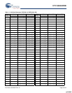
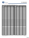
The appropriate entry in Table 14 for the valid data byte or
Table 15 for Special Character byte identify which transmission
character is generated. The current value of the transmitter’s
running disparity is used to select the transmission character
from its corresponding column. For each transmission character
transmitted, a new value of the running disparity is calculated.
This new value is used as the transmitter’s current running
disparity for the next valid data byte or Special Character byte
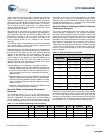
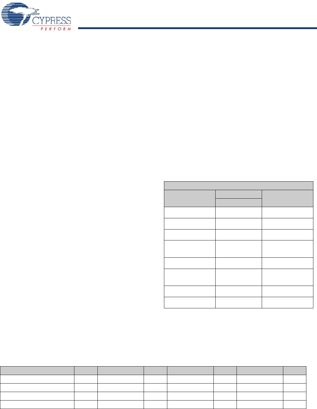
encoded and transmitted. Table 12 shows naming notations and
examples of valid transmission characters.
Use of the Tables for Checking the Validity of Received
Transmission Characters
The column corresponding to the current value of the receiver’s
running disparity is searched for the received transmission
character. If the received transmission character is found in the
proper column, then the transmission character is valid and the
associated data byte or special character code is determined
(decoded). If the received transmission character is not found in
that column, then the transmission character is invalid. This is a
code violation. Independent of the transmission character’s
validity, the received transmission character is used to calculate
a new value of running disparity. The new value is used as the
receiver’s current running disparity for the next received trans-
mission character.
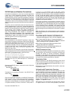
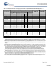
Detection of a code violation does not necessarily show that the
transmission character in which the code violation was detected
is in error. Code violations may result from a prior error that
altered the running disparity of the bit stream which did not result
in a detectable error at the transmission character in which the
error occurred. Table 12 shows an example of this behavior.
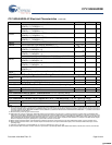
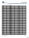
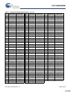
Table 12. Valid Transmission Characters
Data
Byte Name
D
IN
or Q
OUT
Hex Value
765 43210
D0.0 000 00000 00
D1.0 000 00001 01
D2.0 000 00010 02
.
.
.
.
.
.
.
.
D5.2 010 00101 45
.
.
.
.
.
.
.
.
D30.7 111 11110 FE
D31.7 111 11111 FF
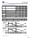
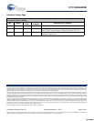
Table 13. Code Violations Resulting from Prior Errors
RD Character RD Character RD Character RD
Transmitted data character – D21.1 – D10.2 – D23.5 +
Transmitted bit stream – 101010 1001 – 010101 0101 – 111010 1010 +
Bit stream after error – 101010 1011 + 010101 0101 + 111010 1010 +
Decoded data character – D21.0 + D10.2 + Code Violation +
[+] Feedback [+] Feedback