


SL811HS
Document 38-08008 Rev. *D Page 7 of 32
USB-A/USB-B Host Transfer Count Register (Read), USB Address (Write) [Address = 04h, 0Ch]. This register has two
different functions depending on whether it is read or written. When read, this register contains the number of bytes remaining
(from Host Base Length value) after a packet is transferred. For example, if the Base Length register is set to 0x040 and an IN
Token was sent to the peripheral device. If, after the transfer is complete, the value of the Host Transfer Count is 0x10, the number
of bytes actually transferred is 0x30. This is considered as an underflow indication.
When written, this register contains the USB Device Address with which the Host communicates.
DA6-DA0 Device address, up to 127 devices can be addressed.
DA7 Reserved bit must be set to zero.
SL811HS Control Registers
The next set of registers are the Control registers and control more of the operation of the chip instead of USB packet type of
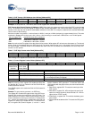
transfers. Tab le 10 is a summary of the control registers.
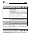
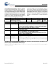
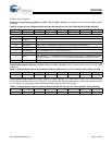
Table 8. USB-A / USB-B Host Transfer Count Register when READ [Address 04h, 0Ch]
Bit 7 Bit 6 Bit 5 Bit 4 Bit 3 Bit 2 Bit 1 Bit 0
HTC7 HTC6 HTC5 HTC4 HTC3 HTC2 HTC1 HTC0
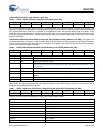
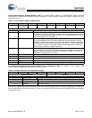
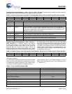
Table 9. USB-A / USB-B USB Address when WRITTEN [Address 04h, 0Ch]
Bit 7 Bit 6 Bit 5 Bit 4 Bit3 Bit 2 Bit 1 Bit 0
0 DA6 DA5 DA4 DA3 DA2 DA1 DA0
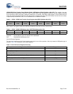
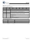
Table 10. SL811HS Control Registers Summary
Register Name SL811H SL811HS (hex) Address
Control Register 1 05h
Interrupt Enable Register 06h
Reserved Register 07h
Status Register 0Dh
SOF Counter LOW (Write)/HW Revision Register (Read) 0Eh
SOF Counter HIGH and Control Register 2 0Fh
Memory Buffer 10h-FFh