


SL811HS
Document 38-08008 Rev. *D Page 9 of 32
Interrupt Enable Register [Address = 06h]. The SL811HS
provides an Interrupt Request Output, which is activated for a
number of conditions. The Interrupt Enable register allows the
user to select conditions that result in an interrupt that is issued
to an external CPU through the INTRQ pin. A separate
Interrupt Status register reflects the reason for the interrupt.
Enabling or disabling these interrupts does not have an effect
on whether or not the corresponding bit in the Interrupt Status
register is set or cleared; it only determines if the interrupt is
routed to the INTRQ pin. The Interrupt Status register is
normally used in conjunction with the Interrupt Enable register
and can be polled in order to determine the conditions that
initiated the interrupt (See the description for the Interrupt
Status Register). When a bit is set to ’1’ the corresponding
interrupt is enabled. So when the enabled interrupt occurs, the
INTRQ pin is asserted. The INTRQ pin is a level interrupt,
meaning it is not deasserted until all enabled interrupts are
cleared.
USB Address Register, Reserved, Address [Address = 07h]. This register is reserved for the device USB Address in Slave
operation. It should not be written by the user in host mode.
Registers 08h-0Ch Host-B registers. Registers 08h-0Ch have the same definition as registers 00h-04h except they apply to
Host-B instead of Host-A.
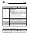
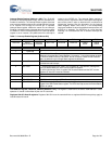
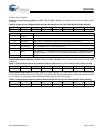
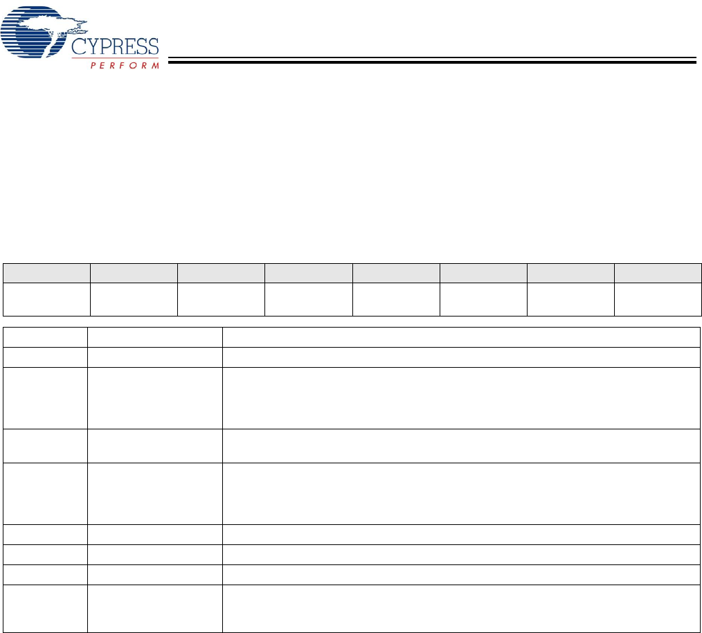
Table 13. Interrupt Enable Register [Address 06h]
Bit 7 Bit 6 Bit 5 Bit 4 Bit 3 Bit 2 Bit 1 Bit 0
Reserved Device
Detect/Resume
Inserted/
Removed
SOF Timer Reserved Reserved USB-B
DONE
USB-A
DONE
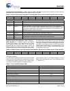
Bit Position Bit Name Function
7 Reserved ‘0’
6 Device Detect/Resume Enable Device Detect/Resume Interrupt.
When bit 6 of register 05h (Control Register 1) is equal to ’1’, bit 6 of this register enables
the Resume Detect Interrupt. Otherwise, this bit is used to enable Device Detection
status as defined in the Interrupt Status register bit definitions.
5 Inserted/Removed Enable Slave Insert/Remove Detection is used to enable/disable the device
inserted/removed interrupt.
4 SOF Timer 1 = Enable Interrupt for SOF Timer. This is typically at 1 mS intervals, although the
timing is determined by the SOF Counter high/low registers.
To use this bit function, bit 0 of register 05h must be enabled and the SOF counter
registers 0E hand 0Fh must be initialized.
3 Reserved ‘0’
2 Reserved ‘0’
1 USB-B DONE USB-B Done Interrupt (see USB-A Done interrupt).
0 USB-A DONE USB-A Done Interrupt. The Done interrupt is triggered by one of the events that are
logged in the USB Packet Status register. The Done interrupt causes the Packet Status
register to update.