


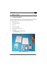

GENERAL FEATURES
3
1
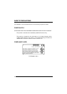
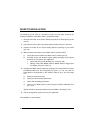
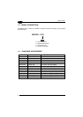
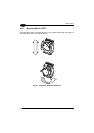
Electrical connection of Power, serial interfaces and I/O signals is provided through a
25-pin connector (see Figure A, 3). In addition there is a 9-pin Auxiliary interface
connector for reader configuration (see Figure A, 2).
The following indicators are located on the top of the reader:
PWR red LED indicates that the reader is connected to the power supply
(see Figure A, 7);
TRIG yellow LED indicates external trigger activity (Figure A, 6); for
details refer to par 2.3.4;
READ red LED signals successful code decoding (Figure A, 5).
It is also used to signal successful startup. At power on this LED
turns on and after a few seconds turns off. If the startup is not
successful, this LED remains on.
COM green LED indicates data transmission on the main serial interface
(Figure A, 4).