


INSTALLATION
21
2
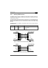
An anti-disturbance filter (debouncing) is implemented on the input, and is software
programmable. The input active state can be defined by the user as well. Refer to the
digital I/O folder in the VisiSet™ Help On Line for further details.
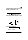
2.3.5 Outputs
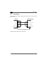
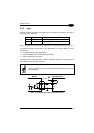
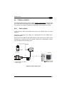
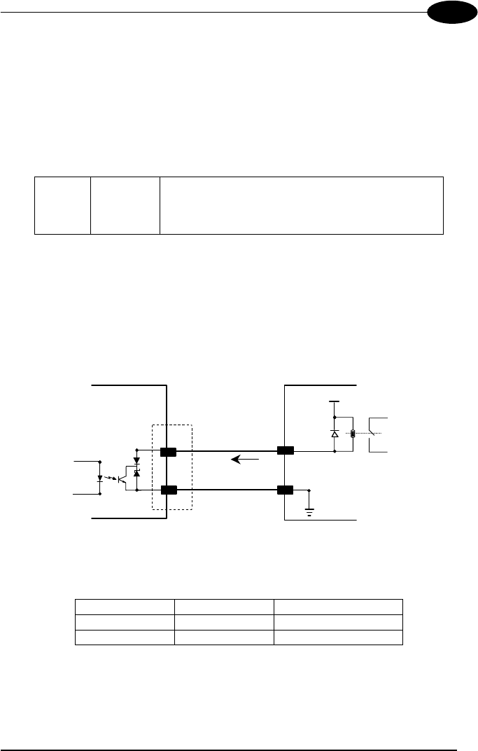
One optocoupled general purpose output is available on the 25-pin connector. The
pinout is the following:
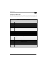
Pin Name Function
16 OUT3+ Configurable digital output 3 - positive pin
17 OUT3- Configurable digital output 3 - negative pin
It is typically used to signal the data collection result. It can also be used to control an
external lighting system
The idle state, the activation/deactivation events and the other configuration
parameters can be defined by the user. Refer to the Digital I/O folder in the VisiSet™
Help On Line for further details.
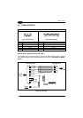
MATRIX
USER INTERFACE
Vext
30 Vdc max
+
-
I
Load
V
Out
Figure 21 - Open Collector Output Connection
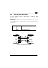
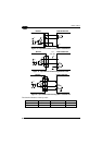
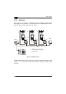
The electrical features of the output are the following:
OUTPUT I
Load
V
Out
Open 0 mA 30 Vdc Max
Closed 10 mA 1.8 Vdc Max
P
D
= V
Out
× I
oLoad
= 170 mW Max.