INSTALLATION
25
2
2.6 TYPICAL LAYOUTS
The following typical layouts refer to system hardware configurations
. However, they
also require the correct setup of the software configuration parameters. Dotted lines
in the figures refer to optional hardware configurations within the particular layout.
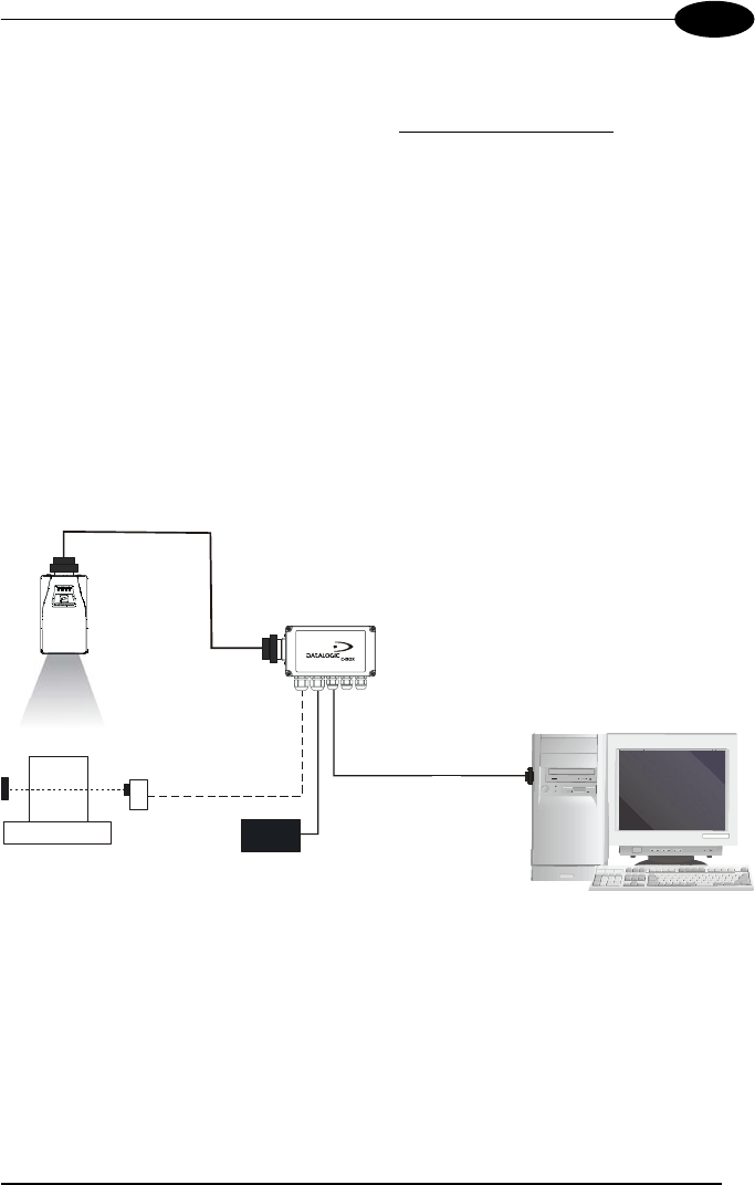
2.6.1 Point-to-Point
In this layout the data is transmitted to the Host on the Matrix-1000 aux serial
interface.
Parameter configuration can always be accomplished using the Matrix-1000
auxiliary interface.
When either Phase Mode or One Shot operating mode are used, the reader can be
activated by an external event (for example a pulse from a photoelectric sensor)
when the object enters its reading zone.
Figure 26 - Point-to-Point Layout
Auxiliary Interface (Local Echo)
External Trigger
C-BOX 100
Matrix-1000™
Local Host
P.S.
PG6000
CAB-600X


