


DATALOGIC DS4300
General Features -
1.3
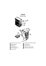
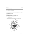
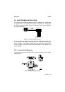
Electrical connection is provided through a cable on the side of the reader;
this cable is terminated with a 25-pin connector (25-pin connector models,
see paragraph 1.3, Figure A,
1
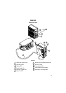
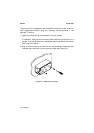
) or by a junction box (junction box models,
see paragraph 1.3, Figure B,
1
).
The laser beam output window is on the right hand side of the scanner
(Figure A/B,
10
). A green LED on the same side indicates the laser is active
(Figure A/B,
9
).
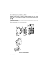
A security system allows the laser to activate only once the motor has
reached the correct rotational speed; consequently the laser beam is
generated after a slight delay from the power on of the scanner.
The four LEDs on the left hand side of the scanner indicate the following:
READY
(red), indicates the reader is connected to the power supply
and the startup was successful. If the startup is not
successful, this LED blinks. (Figure A/B,
3
).
GOOD READ
(red), is used to signal successful barcode decoding. It is
also used in Test mode to signal the decoding percentage
(for details refer to the section "Test Mode" in the WinHost
Help On Line). (Figure A/B,
4
).
EXT TRIG
(yellow), indicates external trigger activity (for details refer to
par.2.4.4. (Figure A/B,
5
).
TX DATA
(green), indicates data transmission on the main serial
output line. (Figure A/B,
6
).
The screw holes on the body of the reader are for mechanical fixture (Figure
A/B,
2
); the screw holes shown in Figure A/B,
11
are to attach accessories
such as the optional 90° mirror.