


DS4300 DATALOGIC
2.8
- Installation
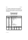
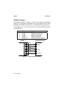
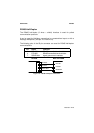
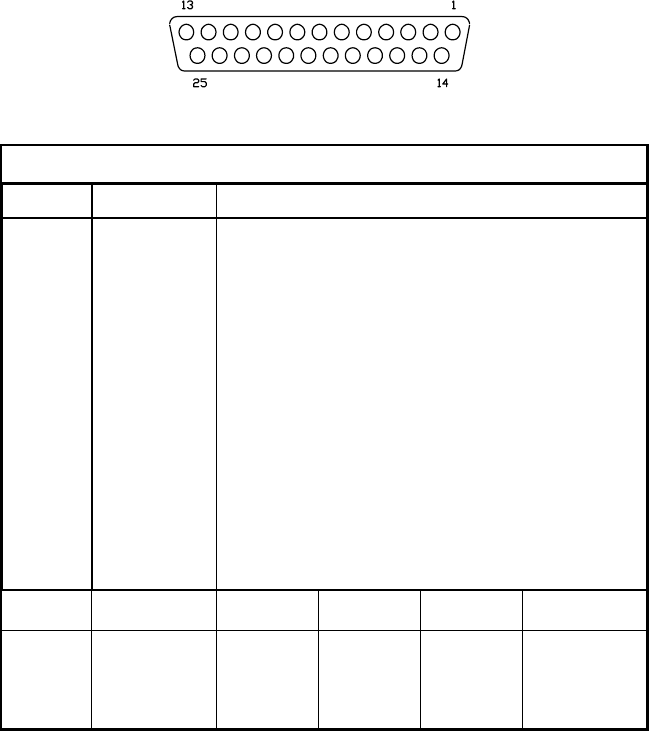
2.4 ELECTRICAL CONNECTIONS FOR 25-PIN MODELS
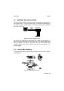
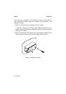
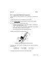
25-pin connector models (see paragraph 1.3) are equipped with a cable
terminated by a 25-pin D-sub connector for connection to the power supply
and input/output signals. The details of the connector pins are indicated in
the following table:
Figure 2.10 - 25-pin D-sub connector
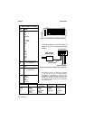
25-pin D-sub connector pinout
Pin Name Function
13 VS Power supply input voltage +
25 GND Power supply input voltage -
1 CHASSIS Chassis Ground
9 VS External Trigger supply voltage +
18 EXT TRIG+ External Trigger +
19 EXT TRIG- External Trigger -
6 IN1+ Input +
10 IN1- Input -
8 OUT1+ Output +
22 OUT1- Output -
11 OUT2+ Output +
12 OUT2- Output -
14 IN2+ Input +
15 IN2- Input -
20 RXAUX Auxiliary RS232 input
21 TXAUX Auxiliary RS232 output
23 SGND Aux Signal Ground Auxiliary interface
24 GND Power supply input voltage -
16 Reserved
17 Reserved
RS232 RS485
full-duplex
RS485
half-duplex
20 mA CL
(INT-24 Only)
2 TX232 TX485+ RTX485+
3 Main interface RX232 RX485+
4 (see par. 2.4.2) RTS232 TX485- RTX485- CLOUT-
5 CTS232 RX485- CLIN-
7 SGND Main SGND Main SGND Main SGND Main