


Standard Cable Pinouts
Product Reference Guide 273
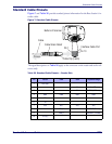
Standard Cable Pinouts
Figure 7 and Table 36 provide standard pinout information for the Base Station’s in-
terface cable.
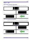
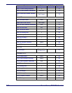
Figure 7. Standard Cable Pinouts
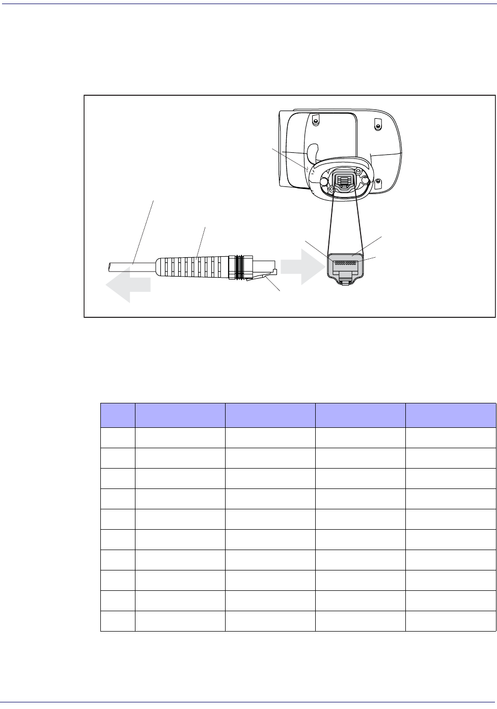
The signal descriptions in Table 36 apply to the connector on the reader and are for ref-
erence only.
Table 36. Standard Cable Pinouts — Reader Side
Pin 1
Pin 10
Cable Clip (Latch)
To Host
Cable
Cable Strain Relief
Bottom of Scanner
Interface Cable Port
Pin RS-232 OEM USB Keyboard Wedge
1RTS (out)
2 D+ CLKIN (KBD side)
3 D- DATAIN (KBD side)
4 GND GND GND GND
5RX
6TX
7 VCC VCC VCC VCC
8 IBM_B CLKOUT (PC side)
9 IBM_A DATAOUT (PC side)
10 CTS (in)