


I-Class 119
Appendix D
GPIO Port Description
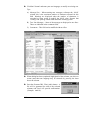
With the optional GPIO PCB, the printer can easily be programmed to interface
with most applicator devices. The GPIO functions are enabled and configured
using the menu system of the printer (see Section 4.1.4). These parameters are
stored in non-volatile memory and saved for subsequent power-ups.
When the GPIO is enabled, the printer will not print a label unless the Start of
Print signal is active. When a label is ready to print and the printer is waiting for
the Start of Print signal the printer will display “WAITING FOR SIGNAL”.
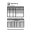
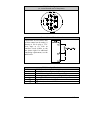
GPIO Port Connections
The GPIO Port interface connector (see next page) is a 9-pin Mini-DIN female
type (e.g., Kycon KMDG-9S-BS) requiring a 9-pin Mini-DIN plug (e.g., Kycon
KMDA-9P). Each GPIO pin function is detailed in the table below:
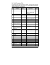
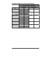
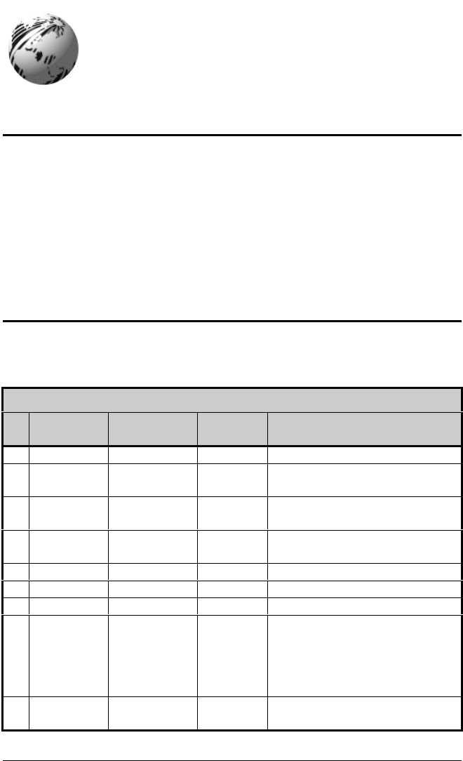
GPIO Pin Functions
Pin
#
Signal
Name
Signal
State
Signal
Direction*
Description
1Vcc +5 VDCOutput Printer +5 VDC
2 Ribbon
Fault
Low Output Goes low when the printer
detects a ribbon fault.
3 Paper
Fault
Low Output Goes low when the printer
detects a label movement fault.
4Printer
Fault
Low Output Goes low when any printer fault
is detected.
5 Spare Reserved Output N/A
6 End of Print Programmable Output Programmable
7 Spare Reserved Input N/A
8 Start of
Print Signal
Low Input When ready to print a label, the
Applicator should set this signal
low for at least 50ms or until the
End of Print signal goes not
active.
9Signal
Ground
Ground N/A N/A
*Signal direction is given relative to the printer.