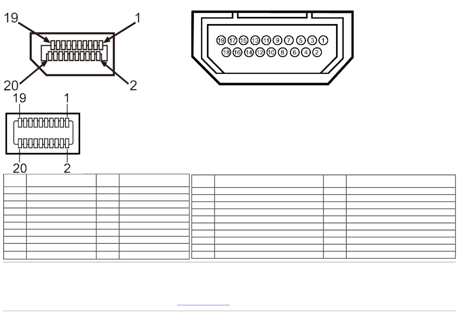
DisplayPort Connector
19-pin HDMI Connector
Pin
Number
20-pin Side of the
monitor connector
Pin
Number
20-pin Side of the
monitor connector
1 ML0(p) 11 GND
2 GND 12 ML3(n)
3 ML0(n) 13 GND
4 ML1(p) 14 GND
5 GND 15 AUX(p)
6 ML1(n) 16 GND
7 ML2(p) 17 AUX(n)
8 GND 18 HPD
9 ML2(n) 19
DP_PWR Return
10 ML3(p) 20
+3.3 V DP_PWR
Pin
Number
19
-pin Side of the monitor connector
(Cable not included)
Pin
Number
19-pin Side of the monitor connector
(Cable not included)
1 TMDS DATA 2+ 11 TMDS CLOCK SHIELD
2 TMDS DATA 2 SHIELD 12 TMDS CLOCK-
3 TMDS DATA 2- 13 Floating
4 TMDS DATA 1+ 14 Floating
5 TMDS DATA 1 SHIELD 15 DDC CLOCK (SDA)
6 TMDS DATA 1- 16 DDC DATA (SDA)
7 TMDS DATA 0+ 17 GROUND
8 TMDS DATA 0 SHIELD 18 +5 V POWER
9 TMDS DATA 0- 19 HOT PLUG DETECT
10 TMDS CLOCK
Plug and Play Capability
You can install the monitor in any Plug and Play-compatible system. The monitor automatically provides the computer system with its Extended Display Identification Data (EDID) using
Display Data Channel (DDC) protocols so the system can configure itself and optimize the monitor settings. Most monitor installations are automatic; you can select different settings if
desired. For more information about changing the monitor settings, see Operating the Monitor
.


