


Back to Contents Page
Video Card/Thermal-Cooling Assembly
Dell™Inspiron™9400ServiceManual
Removing the Video Card/Thermal-Cooling Assembly
Replacing the Video Card/Thermal-Cooling Assembly
Removing the Video Card/Thermal-Cooling Assembly
1. Follow the instructions in Before Working Inside Your Computer.
2. Remove the hinge cover (see Removing the Hinge Cover).
3. Remove the keyboard (see Keyboard).
4. Remove the display assembly (see Removing the Display Assembly).
5. Remove the palm rest (see Removing the Palm Rest).
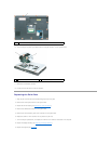
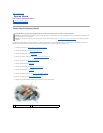
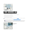
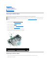
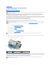
6. Loosen in consecutive order the four captive screws, labeled "1" through "4," that secure the video card/thermal-cooling assembly to the system board.
7. Lift the video card/thermal-cooling assembly from the system board.
Replacing the Video Card/Thermal-Cooling Assembly
NOTE: A removable (or discrete) video card is optional and present only if ordered by the customer. Standard video is integrated on the system board
and is not customer removable.
NOTE: Based on the selections that you made when purchasing your computer, the computer may have different video controller configurations.
Configurations with a removable (discrete) video card include a video card thermal-cooling assembly. Configurations with an integrated video card do
notincludeavideocard/thermal-cooling assembly. To determine the computer's configuration, see the Windows Help and Support Center or see
"Determining Your Computer's Configuration" in your computer's Owner's Manual.
CAUTION: Before you begin the following procedure, see the safety instructions in the Product Information Guide.
NOTICE: To avoid electrostatic discharge, ground yourself by using a wrist grounding strap or by periodically touching an unpainted metal surface (such
as the back panel) on the computer.
NOTICE: To help prevent damage to the system board, remove the main battery (see Before Working Inside Your Computer) before working inside the
computer.
NOTE: Remove the video card/thermal-cooling assembly as a single unit. Do not separate the thermal-cooling assembly from the video card.
1
system board
connector
2
captive screws (4) labeled "1"
through "4"
3
video card/thermal-cooling
assembly
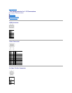
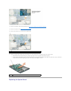
NOTE: Ensure that the video card/thermal-cooling assembly mylar flap rests on top of the processor thermal-cooling assembly when the video
card/thermal-cooling assembly is in place.