


3-4 Dell Dimension XPS D
xxx
Systems Reference and Troubleshooting Guide
5HPRYLQJDQG 5HSODFLQJD)URQW3DQHO
,QVHUW
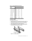
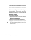
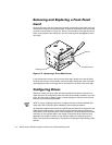
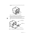
Empty drive bays in the drive cage are covered by a front-panel insert. After you have
removed the computer cover and the bezel, remove the front-panel insert for the bay
you plan to use as shown in Figure 3-3. Press in the two tabs on the right side of the
insert, and rotate the insert toward you until the retaining hook disengages from the
drive cage.
)L JXUH5HPRY LQJD)URQW 3DQHO,QVHUW
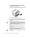
If you permanently remove a drive from the drive cage, reinstall the insert by fitting
the hook into the slot on the left side of the drive cage, rotating the insert into place,
and snapping the tabs on the right side of the insert into the slots in the drive cage.
&RQI LJX UL QJ 'U LYHV
Before you install your drive, check the documentation that came with the drive to
make sure that it is configured to work with other drives already installed in your com-
puter. You may need to change jumper or switch settings on the new drive to avoid
conflicts with drives already installed.
NOTE: If you are installing a tape drive, configure the drive for device address DS4
rather than DS2 or DS3 as may be indicated in the drive documentation.
All enhanced integrated drive electronics (EIDE) devices should be configured for the
Cable Select jumper position, which assigns master and slave status to devices by
their position on the interface cable. In this configuration, the drive attached to the last
connector on the interface cable is the master or boot drive (drive 0) and the drive
attached to the middle connector on the interface cable is the slave drive (drive 1).
Refer to the drive’s documentation for instructions on setting the Cable Select jumper
position.
front-panel insert
tabs (2)
retaining hook