


3-6 Dell Dimension XPS D
xxx
Systems Reference and Troubleshooting Guide
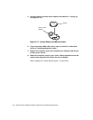
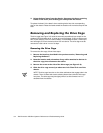
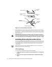
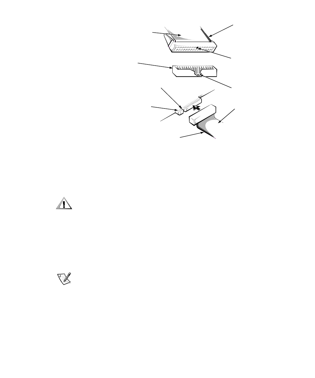
)LJXUH'ULYH,QWHUIDFH&RQQHFWRUV
When attaching the interface cable to a drive, be sure to match the colored strip on
the cable to pin 1 of the drive’s interface connector. For the location of pin 1, look for a
silk-screened “1” next to the interface connector or refer to the documentation that
came with the drive.
&$87,21:KHQFRQQHFWLQJDQLQWHUIDFHFDEOHGRQRWSODFHWKHFRORUHG
VWULSRQWKHFDEOHDZD\IURPSLQRQWKHLQWHUIDFHFRQQHFWRU'RLQJVRSUH
YHQWV GULYHRSHUDWLRQDQGFRXOGGDPDJH WK HFRQ WUROOHUW KHGULYHRUERWK
,QVWDOOLQJ([WHUQDOO\$FFHVVLEOH'ULYHV
The drive cage typically holds diskette drives, tape drives, and CD-ROM drives—up to
two half-height, 5.25-inch devices and two 3.5-inch devices in the mini tower chassis.
In the desktop chassis, it holds up to two half-height, 5.25-inch devices and one
3.5-inch device.
NOTE: Some devices may require additional hardware, such as a mounting kit for
installing a 3.5-inch drive in a 5.25-inch bay.
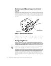
,QFK'ULYHV
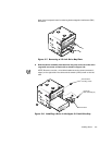
To install a drive in a 5.25-inch drive bay, follow these steps:
3UHSDUHWKHGULYHIRULQVWDOODWLRQDVGHVFULEHGHDUOLHULQ´&RQILJXULQJ
'ULYHVµ
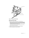
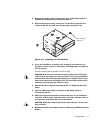
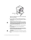
5HPRYHWKHGULYHFDJHDVGHVFULEHGHDUOLHULQ´5HPRYLQJWKH'ULYH
&DJHµ
header connector
on drive
interface
cable
card-edge
connector on drive
colored strip
notch
colored
strip
interface cable
blocked
hole
missing
pin