


1-12 Dell PowerEdge Cluster F-Series SAN Guide
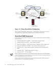
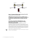
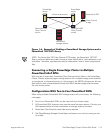
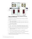
Figure 1-5. Example of Cabling a Single PowerEdge Cluster With
Two PowerVault Fibre Channel Switches
NOTICE: Switch zoning is required if a cluster or standalone server is
already attached to the SAN. Information on using switch zoning with clus-
ter configurations is provided throughout this document. See the Dell
PowerVault system documentation for more information about switch
cabling.
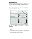
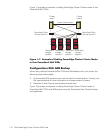
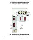
Connecting a PowerVault 130T DLT Library and
PowerVault 35F Fibre Channel Bridge to a Cluster-
Attached PowerVault SAN
You can use the PowerVault 35F Fibre Channel SCSI bridge to support the
PowerVault 130T DLT library or the PowerVault 120T tape autoloader on PowerEdge
Cluster F-Series configurations. Figure 1-6 shows a supported PowerEdge Cluster
F-Series configuration using redundant Fibre Channel switches, Fibre Channel bridge,
and PowerVault 130T DLT library. In this configuration, each of the cluster nodes is
attached to the backup device and the backup local disk resources, as well as to the
owned cluster disk resources. See the storage and tape backup documentation for
more information on configuring these components.
NOTE: Contact the tape backup software vendor for more information on using your
software in a cluster configuration.
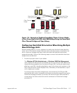
PowerEdge
server
PowerVault
storage system
PowerEdge
server
PowerVault 56F
Fibre Channel
switch
PowerVault 56F
Fibre Channel
switch
cluster interconnect