


1-20 Dell PowerEdge Cluster F-Series SAN Guide
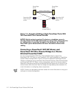
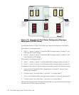
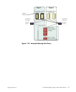
The example shown in Figure 1-10 contains the following configuration information.
Switch fabric 1 comprises switches 1 and 2:
• Zone 1 — server 1, server 2, PowerVault 65
x
F storage system (number 1), and
Fibre Channel-to-SCSI bridge
• Zone 2 — server 3, server 4, PowerVault 65
x
F storage system (number 2), and
Fibre Channel-to-SCSI bridge
• Zone 3 — server 5, server 6, PowerVault 65
x
F storage system (number 3), and
Fibre Channel-to-SCSI bridge
Switch fabric 2 comprises switch 3:
• Zone 1 — server 1, server 2, and PowerVault 65
x
F (number 1)
• Zone 2 — server 3, server 4, and PowerVault 65
x
F (number 2)
Switch fabric 3 comprises switch 4. No zoning is required.
See the
Dell PowerVault 5xF Switches Zoning Guide
for more information on configur-
ing zones on the Fibre Channel switches.
NOTE: The three-cluster configuration requires cascading the PowerVault 51F Fibre
Channel switches. You also can implement this configuration by using two
PowerVault 56F Fibre Channel switches. See the Dell PowerVault 5xF Fibre Channel
switch documentation for more information on cascading the switches.
To implement the zoning in the preceding configuration, perform the following steps:
1. Make sure that the PowerVault 65
x
F storage system (number 2 and 3), server 3,
server 4, server 5, and server 6 are turned off.
2. Configure zone 1 on switch fabric 1 and zone 1 on switch fabric 2.
3. Turn on the PowerVault 65
x
F storage system (number 2), server 3, and server 4.
4. Configure zone 2 on switch fabric 1 and zone 2 on switch fabric 2.
5. Turn on the PowerVault 65
x
F storage system (number 3), server 5, and server 6.
6. Configure zone 3 on switch fabric 1.
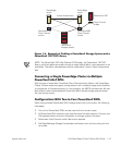
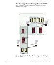
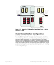
Configurations With Multiple SAN-Attached Clusters,
Each Using Multiple PowerVault 65xF DPEs
Using zoning (as described earlier in this document), a PowerEdge Cluster F-Series
system with multiple storage units can share the same SAN with another cluster. The
applicable zoning rules and guidelines apply, as described in Table 1-1, found earlier in
this document.
Figure 1-11 shows the cabling of a SAN configuration of two PowerEdge Cluster
F-Series clusters. One cluster uses multiple PowerVault 65
x
F DPEs and one cluster
uses a single PowerVault 65
x
F DPE. SAN backup is shown for both clusters.