


1-18 Dell PowerEdge Cluster F-Series SAN Guide
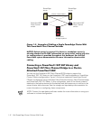
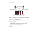
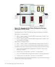
Figure 1-9. Example of a Two-Cluster Configuration Sharing a
PowerVault 130T DLT Library
The example shown in Figure 1-9 contains the following configuration information.
Switch fabric 1 comprises switch 1:
•
Zone 1 — server 1, server 2, PowerVault 65
x
F storage system (number 1), and
Fibre Channel-to-SCSI bridge
•
Zone 2 — server 3, server 4, PowerVault 65
x
F storage system (number 2), and
Fibre Channel-to-SCSI bridge
Switch fabric 2 comprises switch 2:
•
Zone 1 — server 1, server 2, and PowerVault 65
x
F storage system (number 1)
•
Zone 2 — server 3, server 4, and PowerVault 65
x
F storage system (number 2)
To implement the zoning in the preceding configuration, perform the following steps:
1. Ensure that the PowerVault 65
x
F storage system (number 2), server 3, and
server 4 are turned off.
2. Configure zone 1 on switch fabric 1 and zone 1 on switch fabric 2.
3. Turn on the PowerVault 65
x
F storage system (number 2), server 3, and server 4.
4. Configure zone 2 on switch fabric 1 and zone 2 on switch fabric 2.
See the
Dell PowerVault 5xF Switches Zoning Guide
for more information on configur-
ing zones on the Fibre Channel switches.
server 1 server 2
server 3 server 4
PowerVault
Fibre Channel
bridge
PowerVault
tape library
PowerVault
65xF 1
PowerVault
65xF 2
PowerVault
56F Fibre
Channel
switch 2
Zone 1
Zone 2
PowerVault
56F Fibre
Channel
switch 1