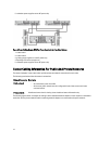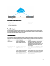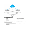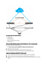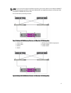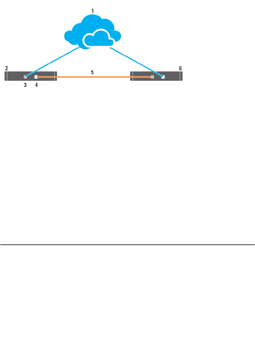
Figure 4. Example of Network Cabling Connection
1. public network
2. cluster node 1
3. public network adapter
4. private network adapter
5. private network
6. cluster node 2
For Public Network
Any network adapter supported by a system running TCP/IP may be used to connect to the public network segments.
You can install additional network adapters to support additional public network segments or to provide redundancy in
the event of a faulty primary network adapter or switch port.
For Private Network
The private network connection to the nodes is provided by a different network adapter in each node. This network is
used for intra-cluster communications. The following table describes the two possible private network configurations.
Method Hardware Components Connection
Network switch Gigabit or 10 Gigabit Ethernet
network adapters and switches
Depending on the hardware, connect the CAT5e
CAT6, CAT6a, or CAT7 cables, the multi-mode
optical cables with Local Connectors (LCs), or the
twinax cables from the network adapters in the
nodes to a switch.
Point-to-Point (two-node
clusters only)
Copper Gigabit network adapters
with RJ-45 connectors
Connect a CAT5e or better (CAT6, CAT6a, or CAT7)
Ethernet cable between the network adapters in
both nodes.
Copper 10 Gigabit Ethernet network
adapters with RJ-45 connectors
Connect a CAT6 or better (CAT6a or CAT7) Ethernet
cable between the network adapters in the nodes.
Copper 10 Gigabit Ethernet network
adapters with SFP+ connectors
Connect a twinax cable between the network
adapters in both nodes.
13


