Dell™ PowerEdge™ R710 Technical Guidebook
11
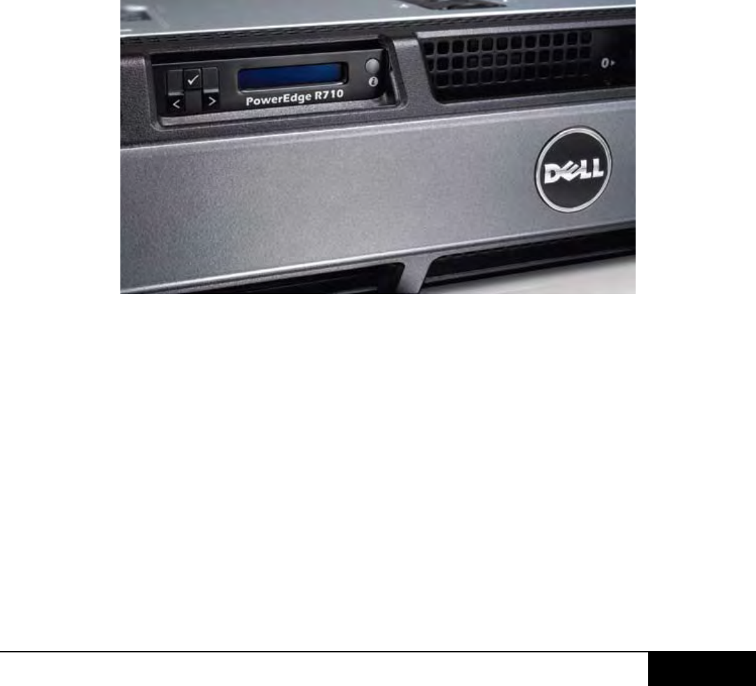
J. Control Panel / LCD
The control panel board is connected to the planar via a 60-wire ribbon cable and a separate 5-wire
cable for USB signals only. The LCD plugs into the control panel through a 20-pin ZIF connector and
flex cable.
The system control panel is located on the front of the system chassis to provide user access to
switches, display, and I/O interfaces. Features of the system control panel are:
•ACPI-compliantpowerbuttonwithanintegratedgreenpowerLED(controlledbyESM)
•128x20pixelLCDwithcontrols
•Twonavigationbuttons
•One-selectbutton
•OnesystemIDbutton
•Non-Maskable-Interrupt(NMI)button(recessed)
•Ambienttemperaturesensor
•TwoexternalUSB2.0connectors(withtwointernalconnectorsdedicatedforUIPS)
•15-pinVGAconnector
The LCD panel is a graphics display controlled by the BMC/ESM. Both ESM and BIOS can send error
codes and messages to the display.
The system’s LCD panel provides system information and status messages to signify when the system is
operating correctly or when the system needs attention.
The LCD backlight lights blue during normal operating conditions and lights amber to indicate an error
condition. When the system is in standby mode, the LCD backlight is o and can be turned on by
pressingtheSelectbuttonontheLCDpanel.TheLCDbacklightwillremainoifthe“NoMessage"
option is selected through the iDRAC6, the LCD panel, or other tools.
BIOShastheabilitytoentera“SecureMode"throughSetup,whichlocksthepowerandNMIbuttons.
Wheninthismode,pressingeitherbuttonhasnoeectbutdoesnotmaskothersourcesofNMIand
power control.
K. Security
I. Cover Latch
A tooled entry latch is provided on the top of the unit to secure the top cover to the chassis


