78 Palm-Rest Assembly
11
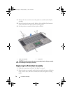
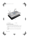
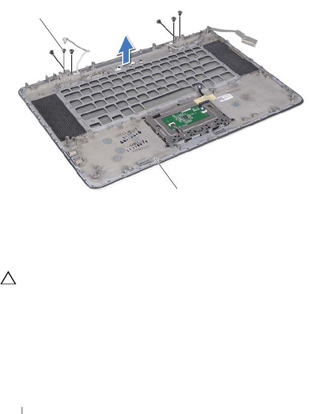
Remove the six screws that secure the palm-rest assembly to the display
assembly.
12
Note the routing of camera cable, display cable, and Mini-Card antenna
cables and remove the cables from the routing guides.
13
Lift the palm-rest assembly off the display assembly.
CAUTION: Carefully separate the palm-rest assembly from the display assembly
to avoid damage to the display assembly.
Replacing the Palm-Rest Assembly
1
Follow the instructions in "Before You Begin" on page 9.
2
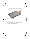
Place the palm-rest assembly on the display assembly and route the display
cable, camera cable, and Mini-Card antenna cables through the routing
guides.
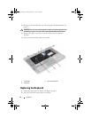
1 palm-rest assembly 2 screws
(6)
2
1
book.book Page 78 Friday, February 21, 2014 12:07 PM


