


10
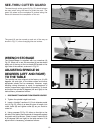
SEE-THRU CUTTER GUARD
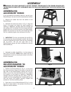
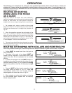
The see-through cutter guard (A) Fig. 20, should always
be used when using the fence to guide the work. The
guard (A) raises as the workpiece is pushed along the
fence and lowers at the completion of the cut.
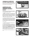
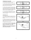
The guard (A) can be moved up and out of the way as
shown in Fig. 21, when changing bits and cutters.
Fig. 20
Fig. 21
A
A
WRENCH STORAGE
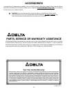
The Router/Shaper is supplied with two wrenches (A)
Fig. 22. When not in use, the wrenches (A) can be stored
safely out of the way on the two hooks (B) located on the
right side of the cabinet, as shown in Fig. 22.
Fig. 22
A
B
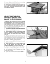
ADJUSTING SPINDLE 90
DEGREES (LEFT AND RIGHT)
TO THE TABLE
The spindle has been aligned at the factory so it is 90
degrees, left and right, to the table surface and further
adjustment should not be necessary. However, rough
handling during shipment or repair or replacement of
certain components might disturb this setting. To check
and adjust the spindle 90 degrees (left and right) to the
table surface, proceed as follows:
1. DISCONNECT MACHINE FROM POWER SOURCE.
2. Tighten the spindle height lock knob.
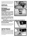
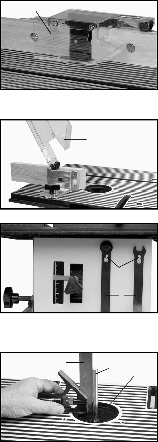
3. Insert a “straight” section of 1/2-inch diameter metal
rod, (A) Fig. 23, which is at least 6 inches in length, into
router collet (B) and tighten collet (B) as you would a
router bit.
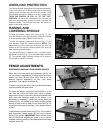
4. Using a square (C) Fig. 23, either on the right or the
left side of the table, place one end of the square against
the metal rod (A) as shown. Check to see if metal rod (A)
is 90 degrees (left and right) to the table surface. If an
adjust-ment is necessary, proceed as follows:
Fig. 23
C
A
B