11
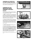
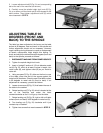
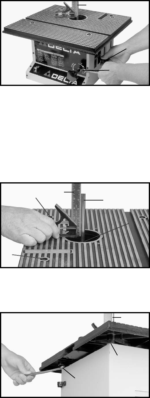
5. Loosen adjustment bolt (D) Fig. 24, and corresponding
bolt at the rear of the machine (not shown.).
6. Carefully move the spindle height lock knob (E) Fig.
24, up or down until the metal rod (A) is 90 degrees to the
table surface. Then tighten adjustment bolts (D) which
were loosened in STEP 5.
Fig. 24
A
E
D
ADJUSTING TABLE 90
DEGREES (FRONT AND
BACK) TO THE SPINDLE
The table has been adjusted at the factory so the table
surface is 90 degrees, front and back, to the spindle and
further adjustment should not be necessary. However,
rough handling during shipment or repair or replacement
of certain components might disturb this setting. To
check and adjust the table surface 90 degrees (front and
back) to the spindle, proceed as follows:
1. DISCONNECT MACHINE FROM POWER SOURCE.
2. Tighten the spindle height lock knob.
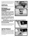
Fig. 25
3. Insert a “straight” section of 1/2 inch diameter metal
rod (A) Fig. 25, which is at least 6 inches in length, into
router collet (B), and tighten collet (B) as you would a
router bit.
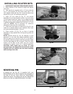
4. Using a square (C) Fig. 25, either on the front or rear
of the table, place one end of the square against the
metal rod (A) as shown. Check to see if the table surface
is 90 degrees to metal rod (A) (front to back). If an
adjustment is necessary, proceed as follows:
5. Loosen two screws (E) Fig. 25, that fasten the rear of
the table to the cabinet.
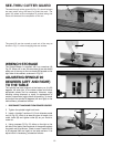
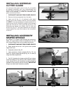
6. Rotate leveling nut (F) Fig. 26, which is located at the
rear of the machine and under the table
counterclockwise as far it it will go up into the table.
7. Rotate leveling nut (G) Fig. 26, right or left until table
surface (front and back) is 90 degrees to metal rod (A).
8. Turn leveling nut (F) Fig. 26, clockwise until it just
contacts top of cabinet.
9. Tighten two screws that were loosened in STEP 5.
Fig. 26
E
E
C
A
B
A
G
F


