


9
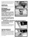
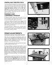
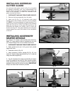
OVERLOAD PROTECTION
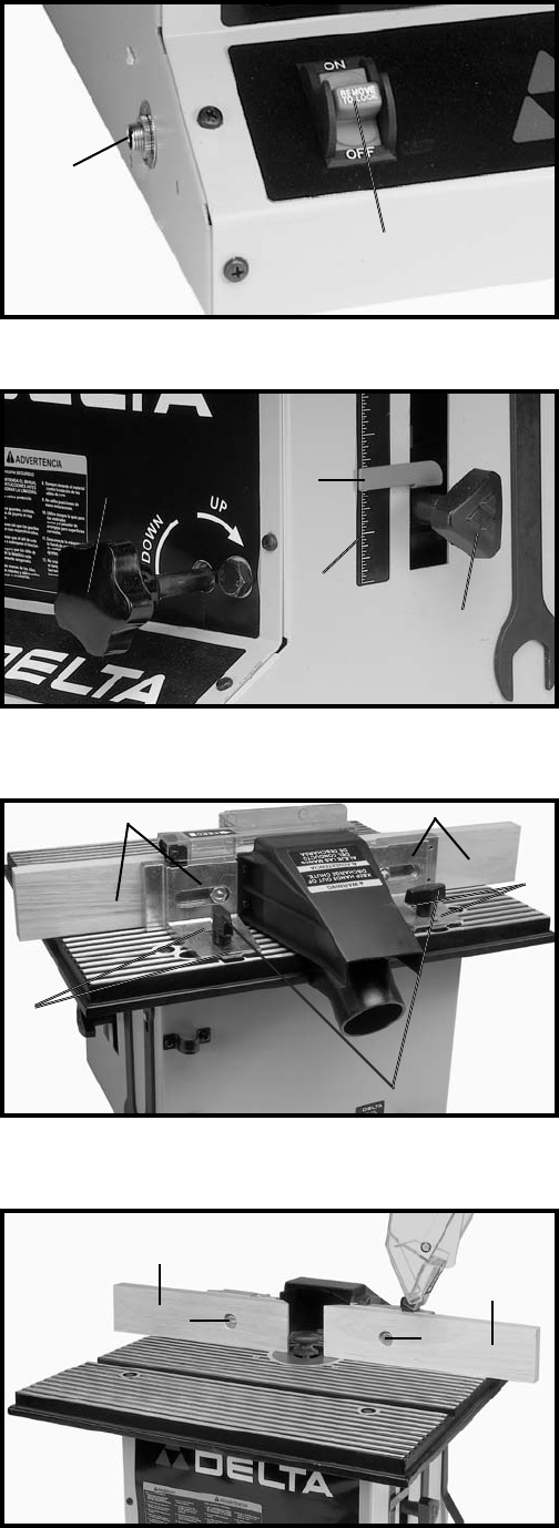
The Router/Shaper is equipped with overload protection.
If the motor shuts off, or fails to start due to overloading
(cutting stock too fast; using dull bits and cutters; using
the machine beyond its capacity or at low voltage, etc.),
TURN THE SWITCH (A) FIG. 16, TO THE “OFF”
POSITION. Let the motor cool three to five minutes and
push the overload reset button (C) which will reset the
overload device. The machine can then be turned on
again in the usual manner.
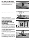
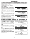
RAISING AND
LOWERING SPINDLE
To raise the spindle, loosen lock knob (A) Fig. 17, and
turn the elevation knob (B) clockwise. When the spindle
is at the desired height, tighten lock knob (A).
To lower the spindle, loosen lock knob (A) Fig. 17, and
turn elevation knob (B) counterclockwise. NOTE: Final
height setting of the cutter should always be from the
bottom to the up position. Always tighten lock knob (A)
after adjusting spindle height.
The Router/Shaper is equipped with a spindle height
adjustment scale (C) Fig. 17, and spindle height indicator
(D). The spindle height indicator moves up or down as
the spindle is raised or lowered.
Fig. 16
Fig. 17
A
C
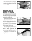
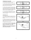
FENCE ADJUSTMENTS
DISCONNECT MACHINE FROM POWER SOURCE.
Either half of the two-piece fence assembly (A) Fig. 18,
can be moved independently. To adjust each fence half,
loosen lock knob (B) and move fence half (A) to the
desired position depending on the work being
performed. Then tighten lock knob (B).
In order to do accurate work, both wooden fence halves
must be parallel with each other.
To check and adjust, move both fence halves in or out
until they are in line with each other. Using a straight
edge check to see if both fence halves are parallel with
each other the complete length of the fences. If an
adjustment is necessary, loosen four socket head cap
screws (C) Fig. 18, located on the fence bracket casting
directly in front of and in back of lock knobs (B) Fig. 18,
and adjust the fences accordingly. Then tighten the four
screws.
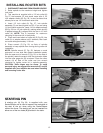
To adjust each wooden fence half (C) Fig. 19, for side to
side movement, loosen screw (D) and move wooden
fence (C) as needed. IMPORTANT: Each wooden fence
half (C) should be adjusted as close to the cutter as
possible, without touching. Once adjustments are made,
retighten screw (D).
Fig. 18
Fig. 19
A
A
B
D
D
C
C
A
B
C
D
C
C