


12
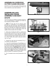
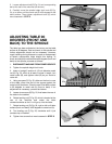
INSTALLING ROUTER BITS
1. DISCONNECT MACHINE FROM POWER SOURCE.
2. Raise spindle to the maximum height and tighten
lock knob.
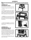
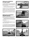
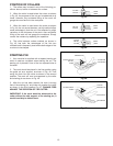
3. This machine is supplied with a 1/2 inch collet (A)
Fig. 27, that accepts 1/2 inch shank router bits. A 1/4
inch adapter sleeve (B) Fig. 28, is also furnished that
allows you to use 1/4 inch shank router bits.
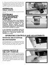
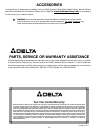
4. Insert 1/2 inch collet (A) Fig. 27, into spindle
assembly (C) and hand tighten nut (D). If you are using
1/4 inch shank router bits, insert 1/4 inch adapter sleeve
(B) Fig. 28, into 1/2 inch collet (A), making certain slot (K)
in adapter sleeve (B) is aligned with the slot in 1/2 inch
collet (A). NOTE: This is important for maximum
clamping of the router bit in the spindle.
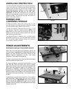
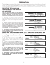
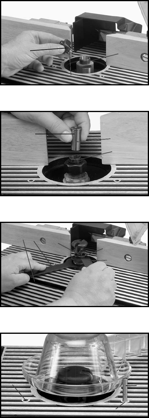
5. Clean and insert shank of router bit (E) Fig. 29, into
collet (A) or adapter sleeve until it bottoms, then back
out router bit approximately 1/16 inch.
6. Place wrench (F) Fig. 29, on flats of spindle
assembly to keep spindle from turning during router bit
installation.
NOTE: Spindle wrench (F) Fig. 29, features a round
protrusion on one side that makes installation easier.
With the open end of wrench (F) Fig. 29, on the flats of
the spindle, rotate the wrench until the protrusion slides
into the miter gage slot (G) as shown. Place the other
wrench (H) on flats of the collet and turn wrench
clockwise to tighten router bit in spindle assembly.
CAUTION: Table ridges may be sharp. To avoid
personal injury, we suggest that wrenches (F) and (H)
supplied with your machine be used when installing
and removing router bits.
Fig. 27
Fig. 28
Fig. 29
Fig. 30
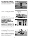
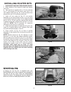
STARTING PIN
A starting pin (A) Fig. 30, is supplied with your
Router/Shaper and is used to support the workpiece at
the start of the cut when using the Router/Shaper
without the fence. The starting pin can be inserted into
either one of the two holes (B) provided in the table.
A
D
C
H
E
F
G
A
B
B
A
A
K
B