


6
ASSEMBLY
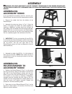
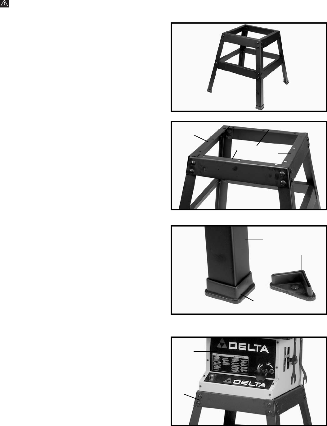
ASSEMBLING
ACCESSORY STAND
If you purchased the accessory stand for use with your
Router/Shaper, the stand must be assembled as follows:
1. Remove the rubber feet from the bottom of the
Router/Shaper.
2. Assemble the stand as shown in Fig. 2. Align the
holes in the stand and fasten the stand together by
inserting a M8X20mm carriage head bolt through the
hole, place a 3/8" flat washer onto the carriage head bolt,
thread a M8 hex nut onto the screw, and hand tighten.
Repeat this process for the thirty one remaining holes.
Do not completely tighten the hardware at this time.
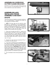
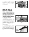
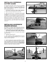
3. IMPORTANT: The four top brackets (A) and (B) Fig.
3, of the stand are the same length; however, the top lips
of the two brackets (A) must fit over the top of brackets
(B), as shown. The left and right side of the
Router/Shaper cabinet will then be fastened to the two
side brackets (A).
4. Assemble a rubber foot (D) Fig. 4, to the bottom of
each leg (E) as shown. NOTE: Each rubber foot (D) is
provided with a hole for mounting the stand to the floor
surface if required.
ASSEMBLING
ROUTER/SHAPER TO
ACCESSORY STAND
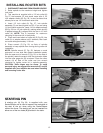
1. Position the Router/Shaper (F) Fig. 5, on the stand
(G) lining up the four holes on the bottom of the left and
right side of the Router/Shaper cabinet with the four
holes on top of the two side brackets (A) Fig. 3. Fasten
the machine to the stand by inserting a M8X20mm
carriage head bolt through the hole, place a 3/8" flat
washer onto the carriage head bolt, thread a M8 hex nut
onto the screw, and tighten securely. Repeat this
process for the three remaining holes.
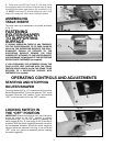
2. Push down on top of Router/Shaper (F) Fig. 5, so the
legs (G) of stand adjust to the surface of the floor and
tighten all stand hardware.
Fig. 2
Fig. 3
Fig. 4
Fig. 5
A
A
B
B
D
E
D
F
G
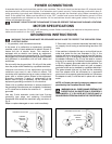
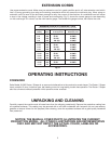
WARNING: FOR YOUR OWN SAFETY, DO NOT CONNECT THE MACHINE TO THE POWER SOURCE UNTIL
THE MACHINE IS COMPLETELY ASSEMBLED AND YOU READ AND UNDERSTAND THE ENTIRE INSTRUCTION
MANUAL.