


Prometheus CPU User Manual V1.44 Page 14
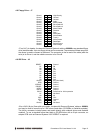
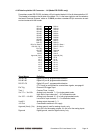
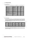
4.10 Data Acquisition I/O Connector – J14 (Model PR-Z32-EA only)
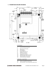
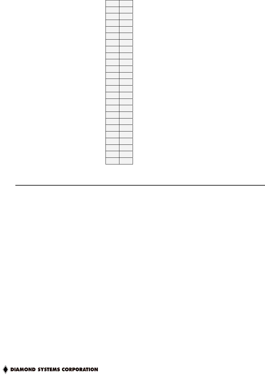
Prometheus model PR-Z32-EA includes a 50-pin header labeled J14 for all data acquisition I/O.
This header is located on the left side of the board. Pin 1 is the lower right pin and is marked on
the board. Diamond Systems’ cable no. C-50-18 provides a standard 50-pin connector at each
end and mates with this header.
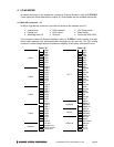
DIO A0 1 2 DIO A1
DIO A2 3 4 DIO A3
DIO A4 5 6 DIO A5
DIO A6 7 8 DIO A7
DIO B0 9 10 DIO B1
DIO B2 11 12 DIO B3
DIO B4 13 14 DIO B5
DIO B6 15 16 DIO B7
DIO C0 17 18 DIO C1
DIO C2 19 20 DIO C3
DIO C4 / Gate 0 21 22 DIO C5 / Gate 1
DIO C6 / Clk 1 23 24 DIO C7 / Out 0
Ext Trig 25 26 Tout 1
+5V Out 27 28 Dground
Vout 0 29 30 Vout 1
Vout 2 31 32 Vout 3
Aground (Vout) 33 34 Aground (Vin)
Vin 0 35 36 Vin 8
Vin 1 37 38 Vin 9
Vin 2 39 40 Vin 10
Vin 3 41 42 Vin 11
Vin 4 43 44 Vin 12
Vin 5 45 46 Vin 13
Vin 6 47 48 Vin 14
Vin 7 49 50 Vin 15
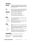
Signal Name Definition
DIO A7-A0 Digital I/O port A; programmable direction
DIO B7-B0 Digital I/O port B; programmable direction
DIO C7-C0 Digital I/O port C; programmable direction
C7-C4 may be configured for counter/timer signals; see page 41
Ext Trig External A/D trigger input
Tout 1 Counter/Timer 1 output
Vin 7/7+ ~ Vin 0/0+ Analog input channels 7 – 0 in single-ended mode;
High side of input channels 7 – 0 in differential mode
Vin 15/7- ~ Vin 8/0- Analog input channels 15 – 8 in both single-ended mode;
Low side of input channels 7 – 0 in differential mode
Vout0-3 Analog output channels 0 – 3
+5V Out Connected to switched +5V supply
Aground (Vout), (Vin) Analog ground; used for analog circuitry only
Vout pin is for the analog outputs; Vin pin is for the analog inputs
Dground Digital ground; used for digital circuitry only