


Prometheus CPU User Manual V1.44 Page 36
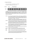
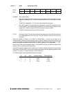
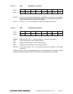
Base + 3 Write Analog Input Gain
Bit No. 7 6 5 4 3 2 1 0
Name X X X X X SCANEN G1 G0
SCANEN Scan mode enable:
1 Each A/D trigger will cause the board to generate an A/D conversion on each
channel in the range LOW – HIGH (the range is set with the channel register in Base
+ 2).
The STS bit (read Base + 3 bit 7) stays high during the entire scan.
0 Each A/D trigger will cause the board to generate a single A/D conversion on the
current channel. The internal channel pointer will increment to the next channel in the
range LOW – HIGH or reset to LOW if the current channel is HIGH.
The STS bit stays high during the A/D conversion.
G1-G0 Analog input gain. The gain is the ratio of the voltage seen by the A/D converter and
the voltage applied to the input pin. The gain setting is the same for all input
channels.
When this register is written to, the WAIT bit (Read Base + 3 bit 6) will go high for 10
microseconds to indicate that the analog input circuit is settling. During this time an A/D
conversion should not be performed because the data will be inaccurate. After writing a new gain
setting, the program should monitor the WAIT bit prior to starting an A/D conversion.
After writing a new channel selection (Base + 2), the WAIT bit is also set, and the program must
monitor it prior to starting an A/D conversion.
The channel and gain registers can be written to in succession without waiting for the intervening
WAIT signal. Only one WAIT period must be observed between the last triggering condition (write
to Base + 2 or Base + 3) and the start of an A/D conversion.
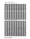
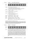
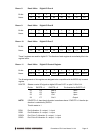
The following table lists the possible analog input ranges:
G1 G0 Gain Unipolar Range Bipolar Range
0 0 1 Invalid ±10V
0 1 2 0-10V ±5V
1 0 4 0-5V ±2.5V
1 1 8 0-2.5V ±1.25V